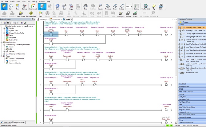
In the very early days of PLC programming ladder diagrams were configured and loaded into a PLC using dedicated hand held programmers. These hand held programmers were extremely slow and tedious to use.
Programming was made a lot easier with the introduction of PC’s and interface software using text based operating systems such as the Microsoft platform MS-DOS. The eventual move away from text based operating systems and into graphical operating systems such as Microsoft Windows has in turn led to the development of graphical PLC programming software.
In fact, the latest software uses many of the operating features that common word processing software utilizes….
- Menu bar and tool bar system.
- Drop down boxes.
- Drag and drop capability.
- Directory like layout and organization.
- Comprehensive search functionality.
- Advanced editing functionality.
- Multiple window for multitasking.
- Data tables for variable declaration.
- On the fly variable declaration.
- Graphical and tabular debugging features.
The latest versions of programming software from the major PLC manufacturers such as Allen Bradley, Siemens, Omron, Schneider, Unitronics, Idec, Koyo and Mitsubishi have made even advanced PLC programming easier than ever.
Ladder logic programming is based on the use of ladder diagrams. Therefore writing such programs for a Programmable Logic Controller (PLC) are very similar to drawing electric relay control circuits. Ladder diagrams consist of two vertical lines that represent the power rails. The circuit components are connected as horizontal lines between the two vertical lines…the rungs of a ladder.
Writing Ladder Logic Programs
In order to learn ladder logic programming there is no need to have experience in other text based programming languages such as C, BASIC, Pascal and FORTRON. However if you are an Electrician, Electrical/Electronic Engineer or Student then you will have a basic understanding of electric circuits and ladder logic programming will be a breeze. If not, don’t worry, the concepts of ladder logic programming are simple enough to grasp and you’ll be writing your first line of code in no time at all!
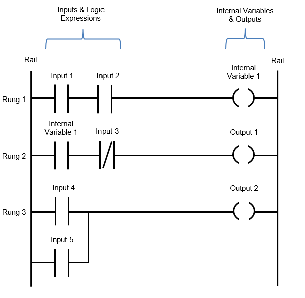
Ladder logic diagrams are structured to look like an electric circuit schematic. The logic flow is from left to right and simulates the current flow in an electric circuit. The basic logic expressions can be arranged to form AND, OR and NOT logic operations by implementing normally open/closed contacts and series/parallel connections.
There is always a left hand side rail and right hand side rail with inputs, logic expressions, internal variables and outputs packed in between. Each element is interconnected to form a line of code, called a rung.
Multiple rungs of code end up looking like a ladder….. Hence the name “Ladder Logic”.
The ladder logic diagram below shows the basic components and how they are arranged when writing a ladder logic program…..
Because ladder logic is a graphical programming language these days the programming software is drag and drop, so it makes it very user friendly. The programming software to write ladder logic code is obtained from the manufacturer and is installed onto your PC. Some manufacturers have free programming software and some require a software license. Be careful because software license=$$$$.
Ladder Logic Programming Rules
Every PLC manufacturer has slightly different ladder logic programming rules when it comes to building the logical expressions contained within a rung. Even a manufacturer with multiple PLC models can have varying rules depending on processing power of each PLC model. But there are seven basic rules that all PLC manufacturers use for ladder logic programming….
1. A PLC scans each rung in the ladder diagram from the left hand side to the right hand side and from the top to the bottom.
2. The PLC scan runs in a repeated cyclic manner where the inputs are monitored, the rung logic evaluated and then the state of the outputs are executed. The scan time is expressed in milliseconds (ms).
3. The logic state of the outputs is evaluated as the program scans through the rungs. But they are only updated at the very end of each PLC scan, simultaneously.
4. There must be at least one input or logic expression at the start of each rung.
5. There must be at least one output at the end of each rung.
6. Each rung in the ladder diagram represents one logic operation in the overall control operation.
7. An input, output or logic expression can be used more than once in the ladder diagram. The same tag name and address is used to label it if used more than once.
To learn more about the PLC scan cycle click here.
Memory Structure For Ladder Logic Programming
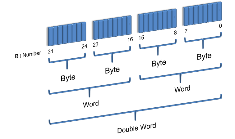
The memory structure for Ladder Logic Programming is just like that of a computer. It is made up of bits, bytes, words and double words.
- Bit – The smallest memory unit. It is either 1 (True) or 0 (False).
- Byte – Is made up of 8 bits.
- Word – Is made up of 16 bits or 2 Bytes.
- Double Word – Is made up of 32 bits, 4 Bytes or 2 Words.
Defining Variables For Use In Ladder Logic Programming
In order for the PLC to process the ladder logic rungs each symbol needs to be allocated to a variable name weather it’s an input, output or internal data. There are three essential elements that must be defined when declaring a variable and one optional element.
- Variable Name – The name must be unique and is used to make the ladder logic easily readable by human beings, such as yourself. There will be restrictions on the length and sometimes characters that can be used.
- Address – the address can be either an Input, Output, Internal or System memory address. The address nomenclature is dependent on the PLC manufacturer.
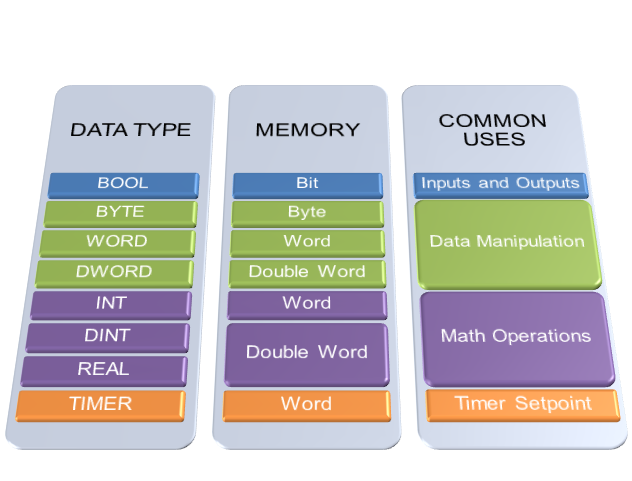
- Data Type – The data type used will depend on the symbol being used and the programming operation required. Defining a variable as a BOOL (Boolean) means it has a binary value, an INT (integer) means it has a whole number value and a REAL (floating point) means it has a number value with a decimal point.
- Comment – Adding a comment is optional, but can assist in describing the variable if the amount of characters in the variable name was insufficient.
The table below shows some standard data types, PLC memory allocation and common uses for each data types.
Different PLC manufacturers use slightly different naming conventions for variables and memory allocation. It’s just a matter of checking the PLC’s help file to determine what to use. Some examples of variable addressing nomenclature for different PLC manufacturers is shown in the table below….

Start Ladder Logic Programming
To start programming you’ll need to get your hands on some software from the PLC manufacturer. Some PLC manufactures have yearly licensing fees $$ for their programming software and others have free programming software.
Regardless of what PLC programming software you use every PLC will have an area in their programming software where the ladder logic programming is done, usually called the “Main Program”. Now-a-days PLC development software for ladder logic is drag and drop….it makes it so easy. Grab the symbol in the toolbar and drag it onto the rung. Next add a variable to the symbol. Most PLC development software allows you to declare variable as you add symbols.
Remember to add lots of descriptive comments to each rung. It helps with readability and trouble shooting.
It’s a good idea to keep each rung as simple as possible. Cramming too much into a rung can save on memory but it can create a really complex network of logic that can come back and bite you if you need to return at a later date to upgrade or modify your program.
Trust me….you’ll spend ages trying to figure out the monster you’ve created….ouch!
A well written PLC program will ensure your machine or plant will be highly productive, efficient and with low downtime.
Ladder Logic Programming with Sub-Routines
If the program starts to get quite large then addition of sub-routines are recommended. Some PLC models will also have additional areas where the sub-routine programming is done. Either way subroutines can help your ladder logic programming to be easier to read and assist in troubleshoot by providing a way to organize your code into kind of a filing system.
It’s up to you with regards to naming your subroutines. Remember to create sub routines so that you can group all the same type of code in the one place. Some examples of possible sub routines that can be created are…..
- Main Program
- Sequence Steps
- Motor control
- Fault logic
- Interlock logic
- Analogue scaling
Upload And Download Your Ladder Logic Program
Once your ladder logic program is complete you will need to compile the program. The compile, button is usually located in the toolbar. Compiling the program is just checking for syntax, memory and program structural errors. If there are any issues then error messages will be generated that directly points you to the source of the problem.
Once all the errors are fixed it’s time to download to the PLC. The download button is also usually located in the toolbar of the PLC programming software.
PLC Upload Vs Download
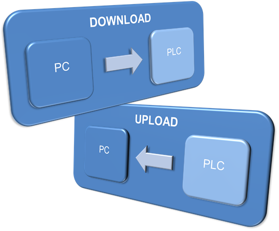
The PLC is taken to be the point of reference when we talk about program upload and download. Therefore a PLC Download is transferring the program from your PC to the PLC. While a PLC Upload is transferring the program from the PLC to your PC.
Remember To Set Your Ladder Logic Programming To RUN MODE
So you’ve written the ladder logic program, compiled and downloaded to the PLC, but nothing is happening ……….You need to put the PLC into run mode.
Run mode simply starts the PLC scan cycle.
Some PLC’s have a key switch, others have a soft switch done through the PLC development software (usually some buttons in the toolbar). Either way there should be a RUN light that illuminates on the face of the PLC……now you’re cooking!
Debugging Your Ladder Logic Program
Ladder logic is great for debugging your program. When you place the PLC development software in ONLINE mode the symbols in each rung highlight in real time when their respective conditions are TRUE. So if your rung is fully highlighted all way up to your output, then the output is TRUE…… Just like current flow in an electric circuit.
To assist in testing and commissioning you can also force the state of binary variables to TRUE or FALSE and also force analogue variables to a specific value. This can be very useful, but remember to release all the forced variables after you’ve finished testing your program.
Most PLC programming software have the facility to create variable tables which display the variable information and status or value. This gives you a handy display area for analyzing the status and value of the variables instead of scrolling up and down through your rungs of code.
With the latest programming software multiple windows, with the program and variables table, can be displayed simultaneously which comes in super handy when debugging.
Ladder Logic Programming IEC 61131 Standards
International PLC programming standards are contained in IEC 61131 in which ladder logic programming standards are outlined in IEC 61131 section 3 (IEC 61131-3).
Don’t panic….you don’t have to start learning the IEC 61131-3 standards. All the IEC61131-3 standard means is that if you learn ladder logic then you’ll be able to apply it to any manufacturers PLC’s. Good news, right!!
You see, ladder logic and PLC’s have become an extremely popular alternative for automation control system compared to traditional methods. As it’s popularity grew, so did the amount of companies manufacturing PLCs. Soon there were a multitude of manufacturers each with their own version of a PLC programming language. So the International Electrotechnical Commission published a PLC programming standard to bring commonality to the various versions of each programming language found in all the different manufactures PLC’s.
The ladder logic programming language is denoted by (LD) in the IEC 61131-3 standard. There are other programming languages that are contained in the IEC 61131-3 standard, but you will find that the most common PLC language is ladder logic. It is by far the best “foot in the door” when it comes to PLC programming and it can accomplish the majority of application control tasks.
Nowadays most PLC manufacturers fully or partially support the IEC6111 standard. There is no obligation for manufactures to comply with the IEC 61131 standard and in fact some PLC manufacturers have designed their programming software to be more user friendly than the IEC 61131-3 standard. So it’s good to be aware that the IEC 61131 standard for PLC programming exists, but there’s no need to get too caught up in it all!
Ladder Logic Programming Samples
The best way to progress from this point is to dive into some ladder logic programming samples. We can think of a sample ladder logic program as a piece of the overall programming puzzle. If we create enough ladder logic programming pieces and join them together we can form a complete program.
In the next section we will begin to investigate programming examples with one of the most important pieces of ladder logic you’ll ever use.
To go to the next section click here.

