A ladder logic simulator is a software application that lets you simulate the operation of a PLC ladder diagram with a personal computer, mobile phone or tablet. It allows you to test your PLC ladder diagram without the need to purchase any PLC hardware.
A ladder logic simulator also has the ability to control the state of the inputs, outputs and internal variables. This means that input and output devices do not need to be purchased or connected to the PLC.
You can save time and money by using a ladder logic simulator to test your ladder diagram.
Saving 100’s, even 1000’s of dollars on purchasing a PLC sounds like a good idea. Especially if you are just starting out on the journey to learn ladder logic programming.
Ladder Logic Simulator Free Download
The Do-more Designer PLC Programming Simulator is by far the easiest, most flexible, feature packed ladder logic simulator that’s out there at the moment for a PC.
It’s free to download with no registration required and genuinely no strings attached.
The Do-more Designer is actually the PLC programming software used for the Do-more PLC by Automation Direct.
The actual PLC Programming Simulator is built into the Do-more Designer software and is a full-featured programming tool, not just a demo version.
The beauty of using actual PLC programming software with a built in PLC simulator is that it allows you to get a feel for what real PLC programming software is like.
So when you transition to using real life PLC hardware the learning curve is much easier. Even if you are using different PLC hardware.
The Do-more Designer Software is compatible with Windows Vista, Windows 7, Windows 8 and Windows 10 operating systems.
The minimum system requirements are a 1GHz single core CPU with 1GB RAM and 330Mb of storage.
To get the Do-more Designer PLC Ladder Logic Simulator Free Download from Automation Direct click here.
Ladder Logic Simulator Example
Once you’ve installed the software it’s time to get stuck into a PLC ladder logic simulator example.
Let’s do a ladder logic latch example with the PLC simulator.
For an explanation on ladder logic latch programming click here.
Create a New Project To Use With the PLC Simulator
Run the application and choose New Offline Project….
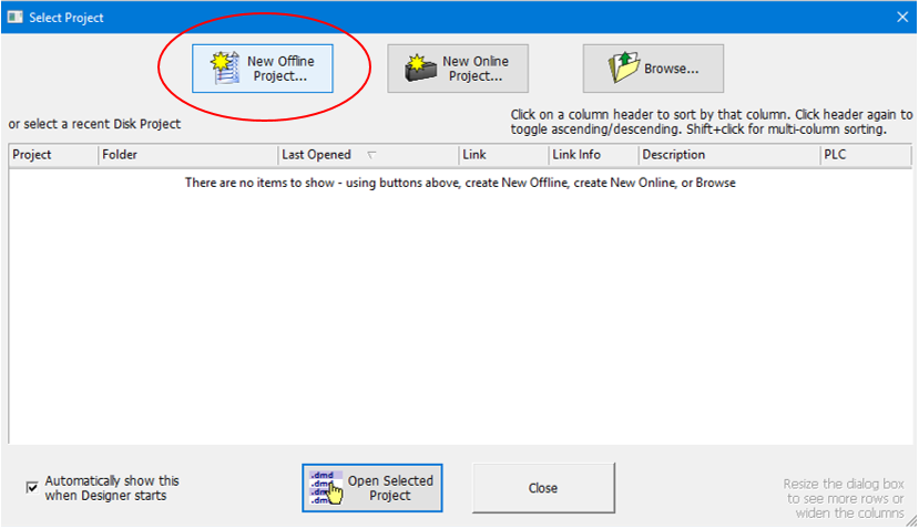
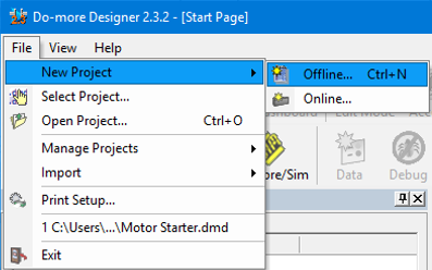
If the “Select Project” dialog box does not automatically pop up then go to File, New Project and select Offline…
In the “New Offline Project” dialogue box select “Do-more Simulator” in the Do-more Hardware Class. Then name the project, select the directory location and click OK….
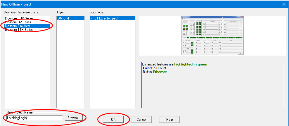
Well done. We have just created a new project file for the PLC simulator.
PLC Simulator Layout
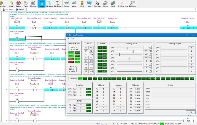
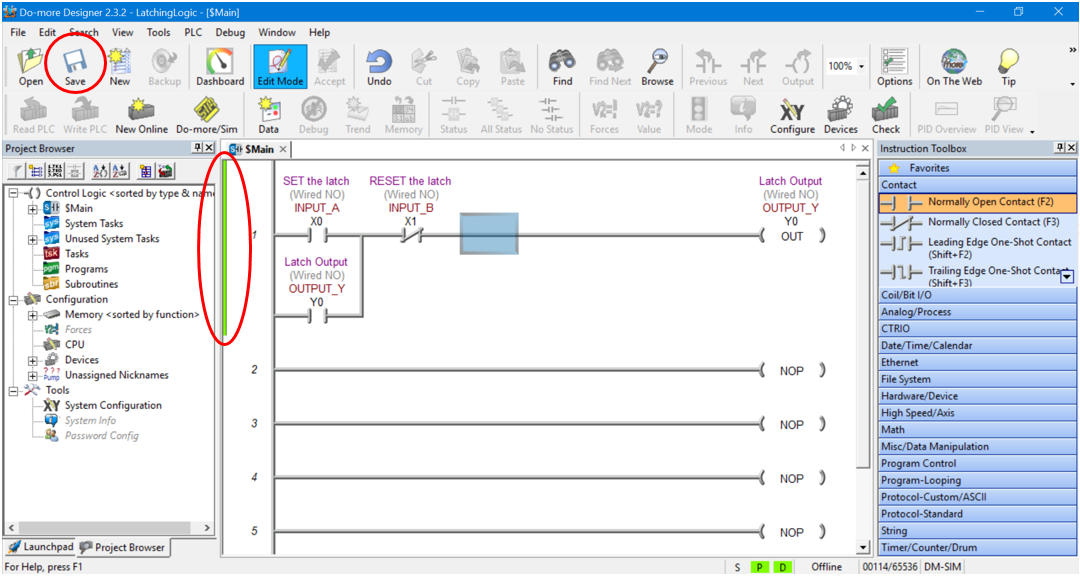
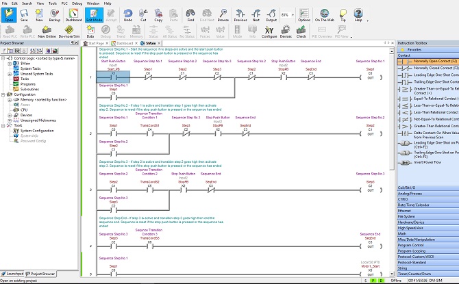
When your newly created project first fires up the layout should be similar to below….
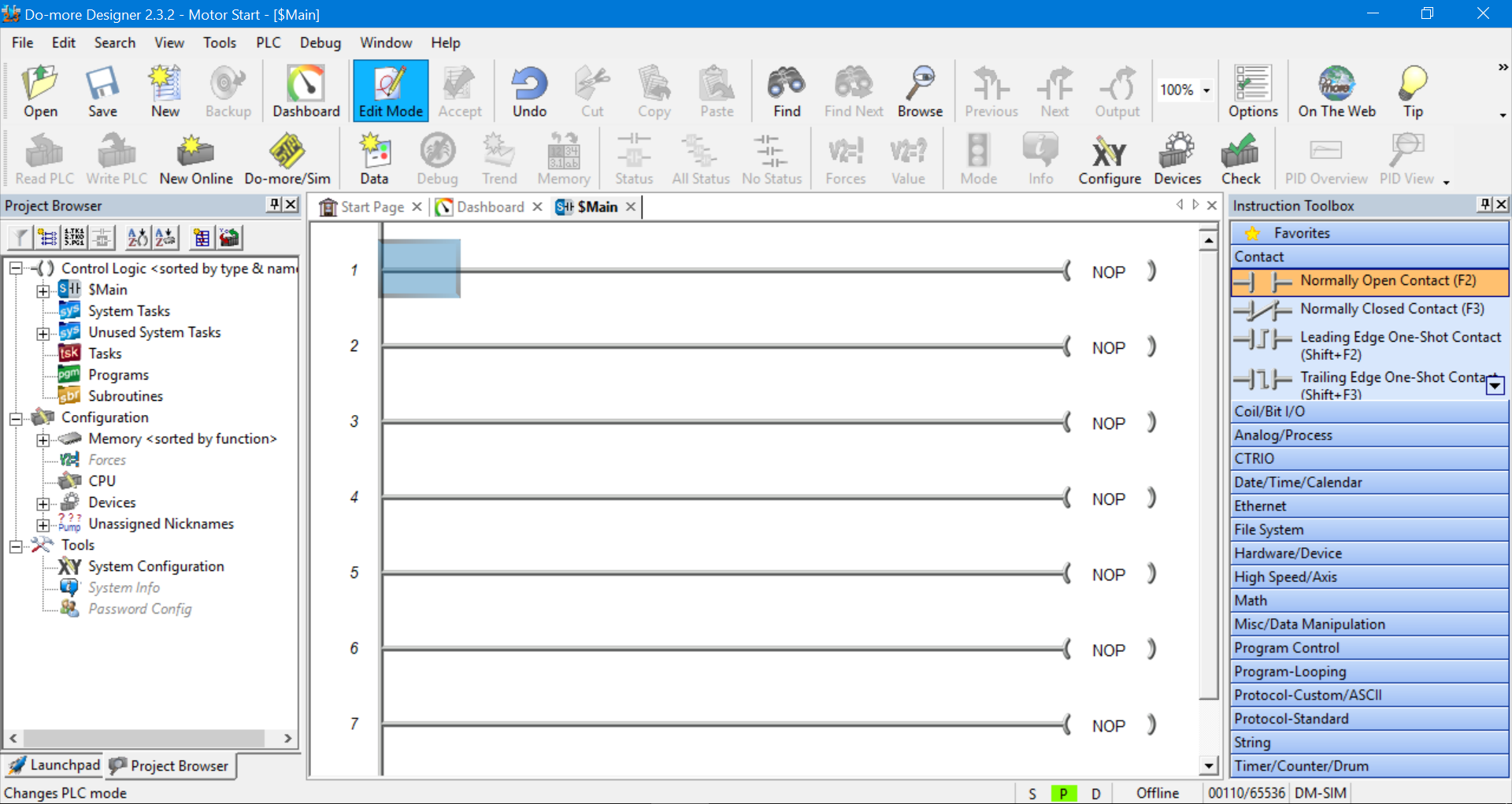
The Main Toolbar is at the top, the Project Browser is on the left, the Instruction Toolbox is on the right and the Status Bar is down the bottom.
The Main Toolbar and Project Browser can be hidden or made visible by selecting the View menu in the Main Toolbar. And the Instruction Toolbox can be hidden or made visible by selecting the Edit menu in the Main Toolbar.
We should have the Main program displayed. It will have a bunch of rungs connected to NOP (no operation) outputs.
We can close the Dashboard and Start Page tabs (next to the Main tab) to simplify things.
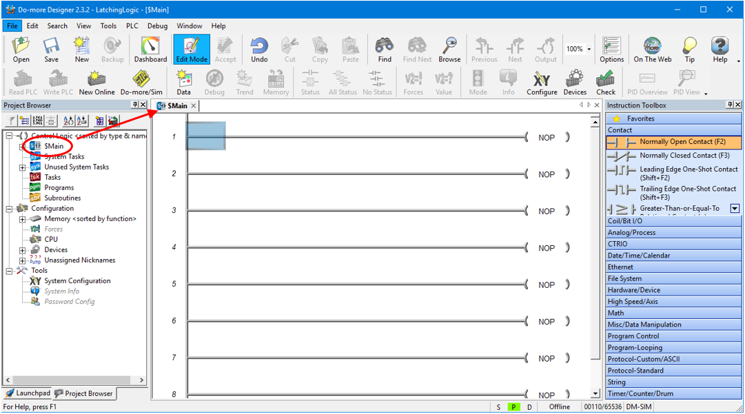
If you accidentally close the Main program just double click on “Main” in the Project Browser on the left hand side…
The Do-more Designer is fully functional PLC programming software. There is an awful lot that we can do with this kind of software with regards to structuring and organizing our program.
Because we are using the PLC programming simulator we will be limited to the amount of ladder logic programming that we can simulate at any one time. So we don’t need to fully utilize all of the software’s features.
We will only need to do our ladder logic programming in the Main program. There is no need to create extra programs or sub routines at this stage. We’ll stick to the essentials for now.
Using the Ladder Diagram Editor
So let’s get started with our first piece of ladder logic programming.
If Edit Mode is not highlighted in the Main Toolbar then click on it to enable program editing….
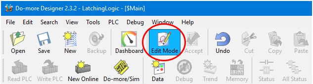
This will also pop up the Instruction Toolbox on the right hand side.
Please note that the Do-more PLC simulator calls a symbol an instruction. Don’t worry, the two terms, instructions and symbols, are readily interchangeable.
Grab a Normally Open contact symbol (or instruction) from the Instruction Tool bar and drag and drop it into the start of the first rung….
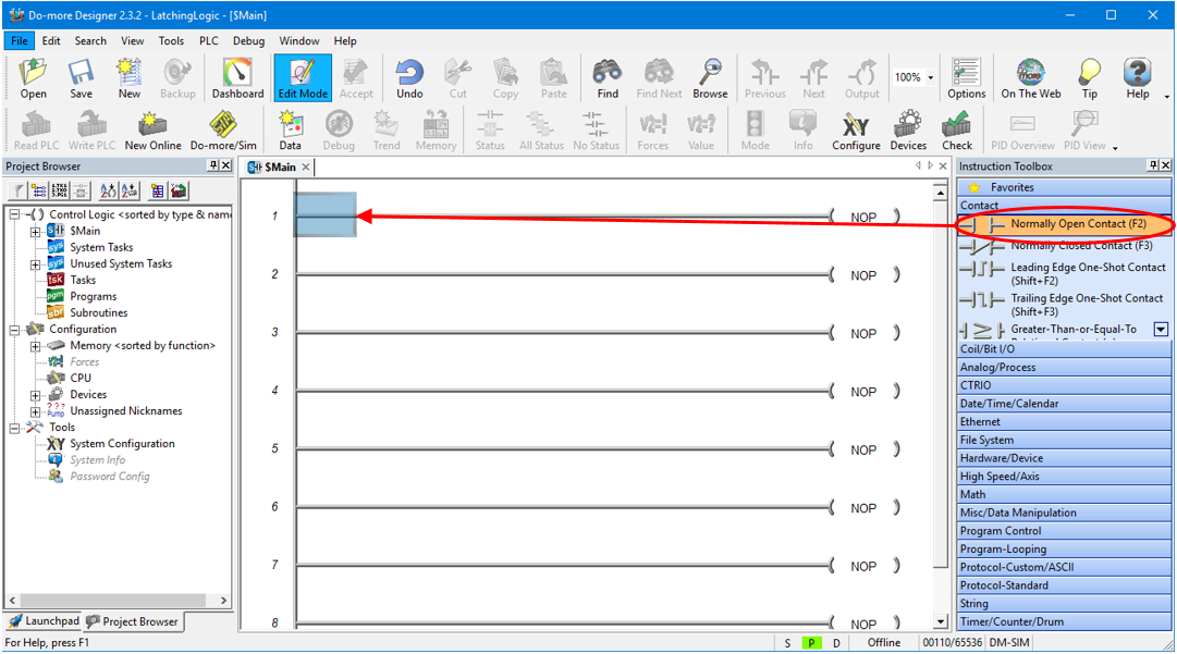
If we drop the instruction in the wrong spot or have accidentally dropped the wrong instruction then we can cancel it by hitting the ESC key.
If we have already declared the symbol and want to delete it then select the symbol and hit the Delete key.
A dialogue box will popup so we can declare the symbol.
PLC Simulator Input Symbol Declaration
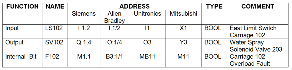
The Do-more PLC programming simulator allocates symbol addressing the same as the actual real life PLC.
In this example we will be declaring digital inputs and digital outputs as per below….
X0-2047 (Digital Inputs)
Y0-2047 (Digital Outputs)
Because this PLC simulator is fully featured there are other symbol declarations possible, but we will not be using them for this example….
C0-2047 (Digital Internal Variables)
RX0-255 (Real Analog Inputs)
WX0-255 (Signed Word Analog Inputs )
RY0-255 (Real Analog Outputs )
WY0-255 (Signed Word Analog Outputs
R0-2047 (Real Internal Analog Variables)
V0-2047 (Unsigned Word Internal Analog Variables)
N0-2047 (Signed Word Internal Analog Variables )
D0-2047 (Signed Double Word Internal Analog Variables)
T0-255 (Timers )
CT0-255 (Counters)
ST0-1023 (System Variables)
To declare the instruction as a digital input type X0 into the text field and click on the magnifying glass icon. Don’t worry about the yellow popup box for now, you can close it if you want….
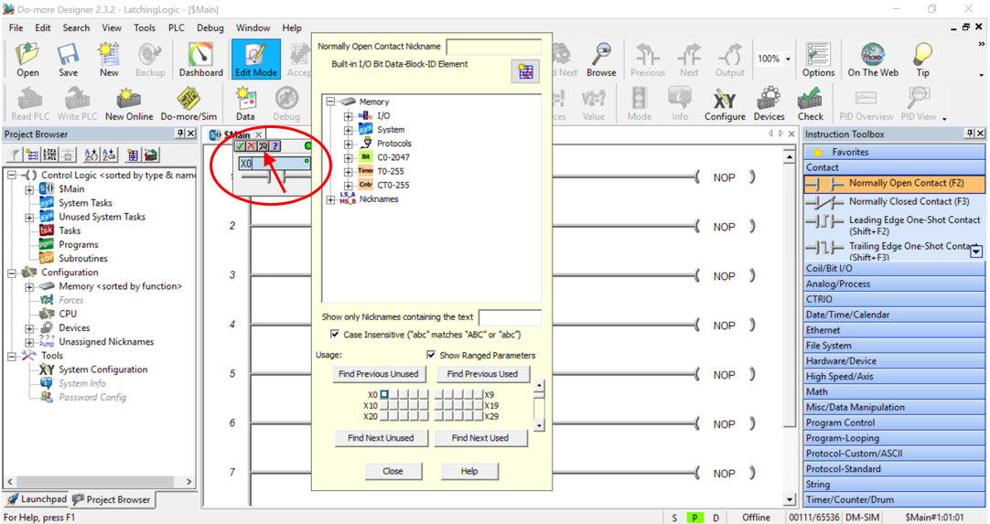
After the magnifying glass icon is selected the Element Browser table will popup. Fill it in as per below….
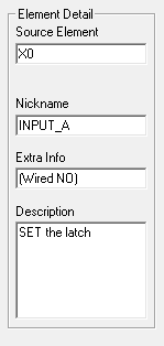
And then click Select.…
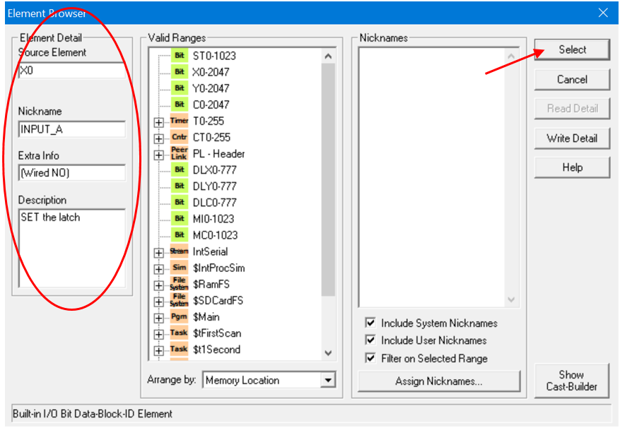
Save the changes when prompted.
Then click on the tick icon to accept the instruction declaration…
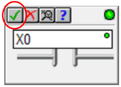
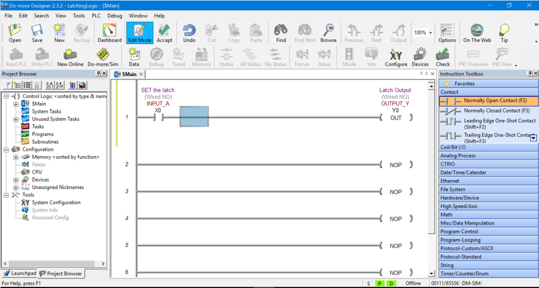
Now, the first rung of the ladder diagram should have the normally open contact with all the declared information displayed above it, as per below…..

PLC Simulator Output Symbol Declaration
So let’s add an output to the first rung.
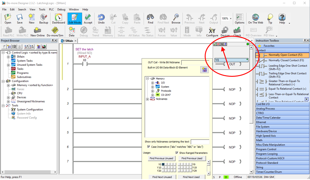
Double click on the NOP output on the right hand side of the first rung. The instruction declaration pop up box appears.
This time we need to declare an output address, so type Y0 into the text field. Then click the magnifying glass….
After the magnifying glass icon is selected the Element Browser table will popup. Fill it in as per below….
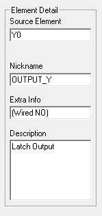
And then click Select.…
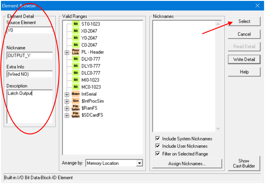
Save the changes when prompted.
Then click on the tick icon to accept the instruction declaration…
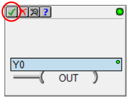
The first rung of the ladder diagram should now have the normally open contact in series with the output. All the declaration information should be displayed above each ladder logic symbol….
Adding More Symbols Using the Ladder Diagram Editor
Let’s continue with adding the rest of the ladder diagram symbols for the Latching logic.
This time we need to drag and drop a normally closed contact into the position next to INPUT A.
Use the same procedure as above to declare the instruction. This time declare it as input X1 as per the information below…
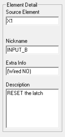
Remember to click Select, Save the changes if prompted and then click on the tick icon to accept the instruction declaration.
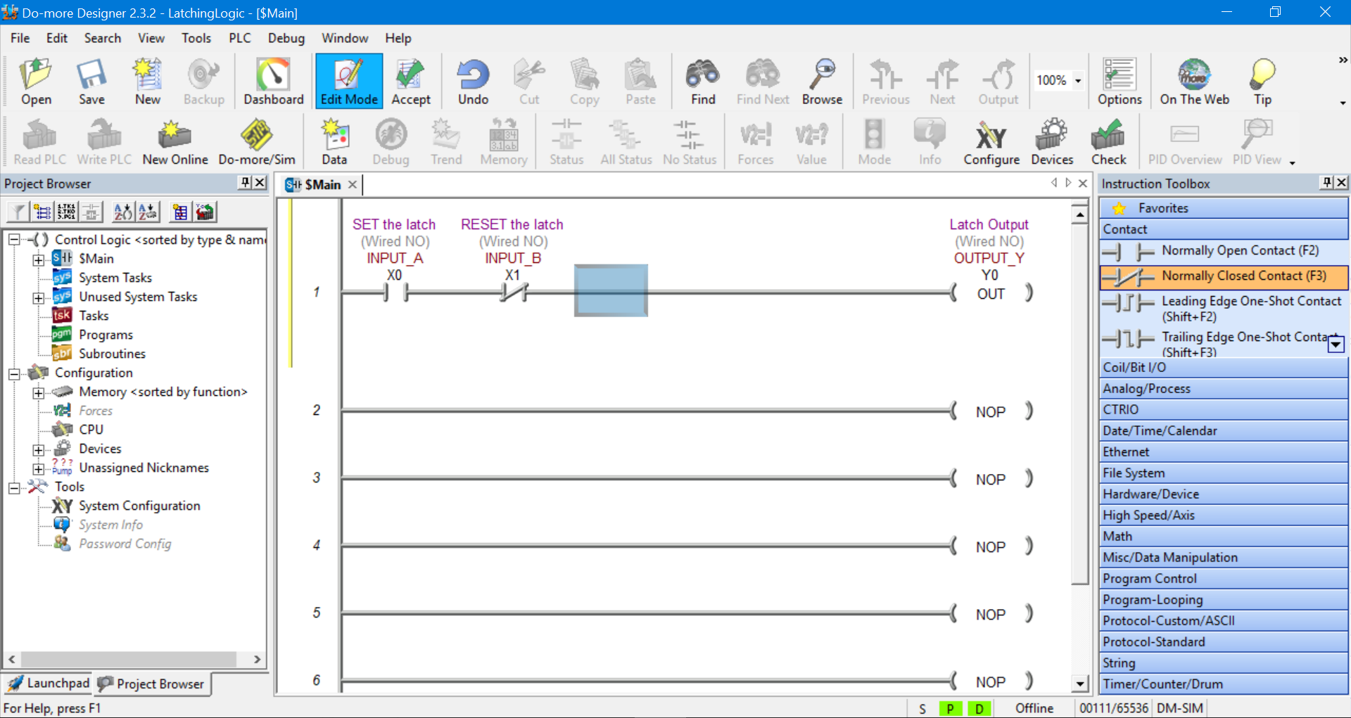
Now we’re cooking. The Main program should look like this….
Adding a Symbol Branch Using the Ladder Diagram Editor
Time to add the last ladder diagram symbol to complete our ladder logic latch PLC simulator example.
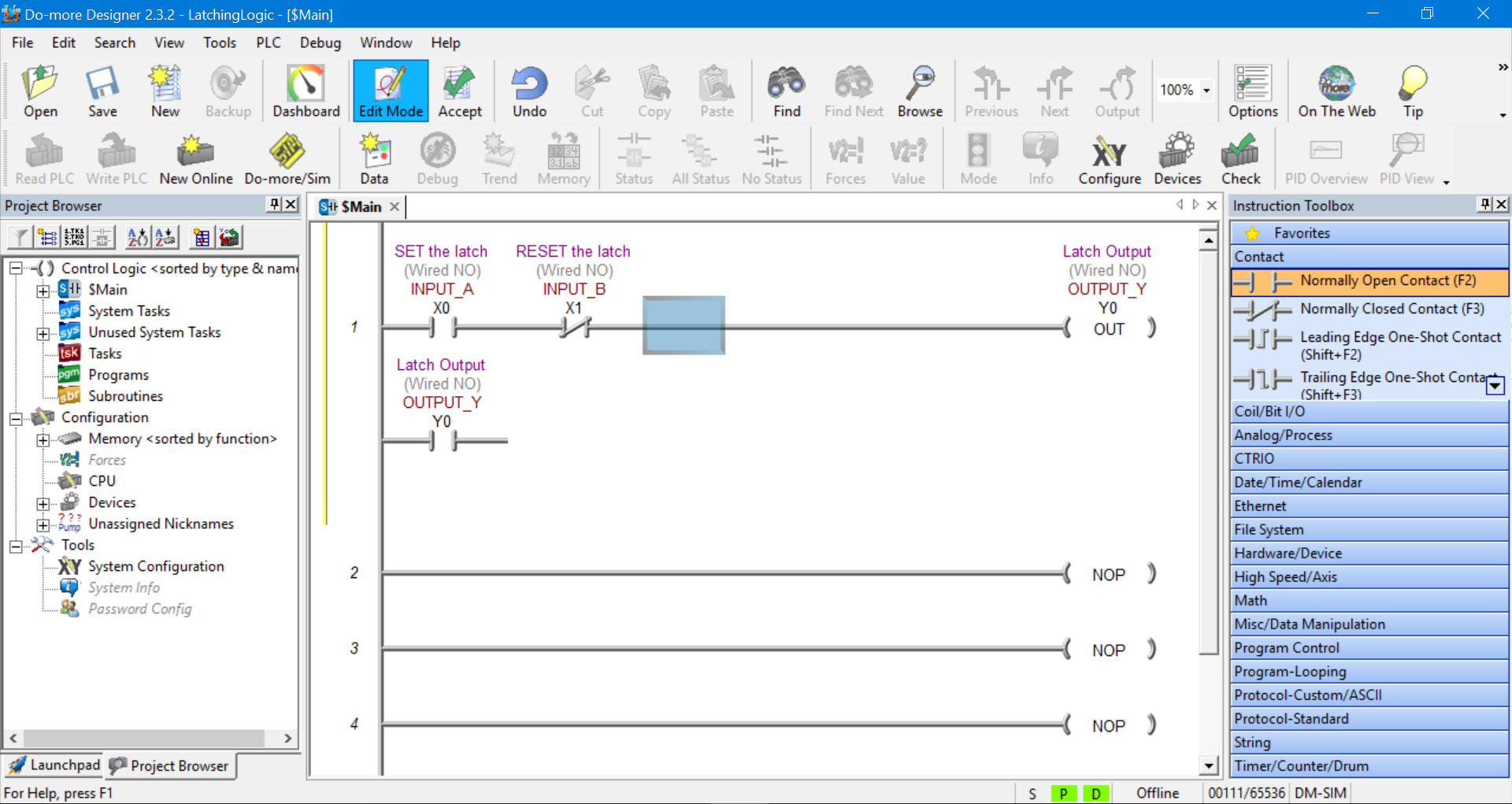
Grab a normally open contact and drag and drop it into the area just below the INPUT A symbol.
This symbol has already been declare so we do not need to declare it again. Just enter Y0 in the instruction declaration text box and hit the tick icon or press enter.
The Main program should look like this….
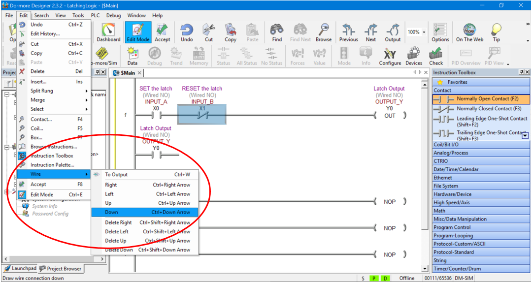
Notice there is a connection missing between the new symbol just added and rung 1.
We can add that connection by clicking on INPUT B symbol to select it. Then going to the main toolbar and selecting Edit, Wire and the Down.
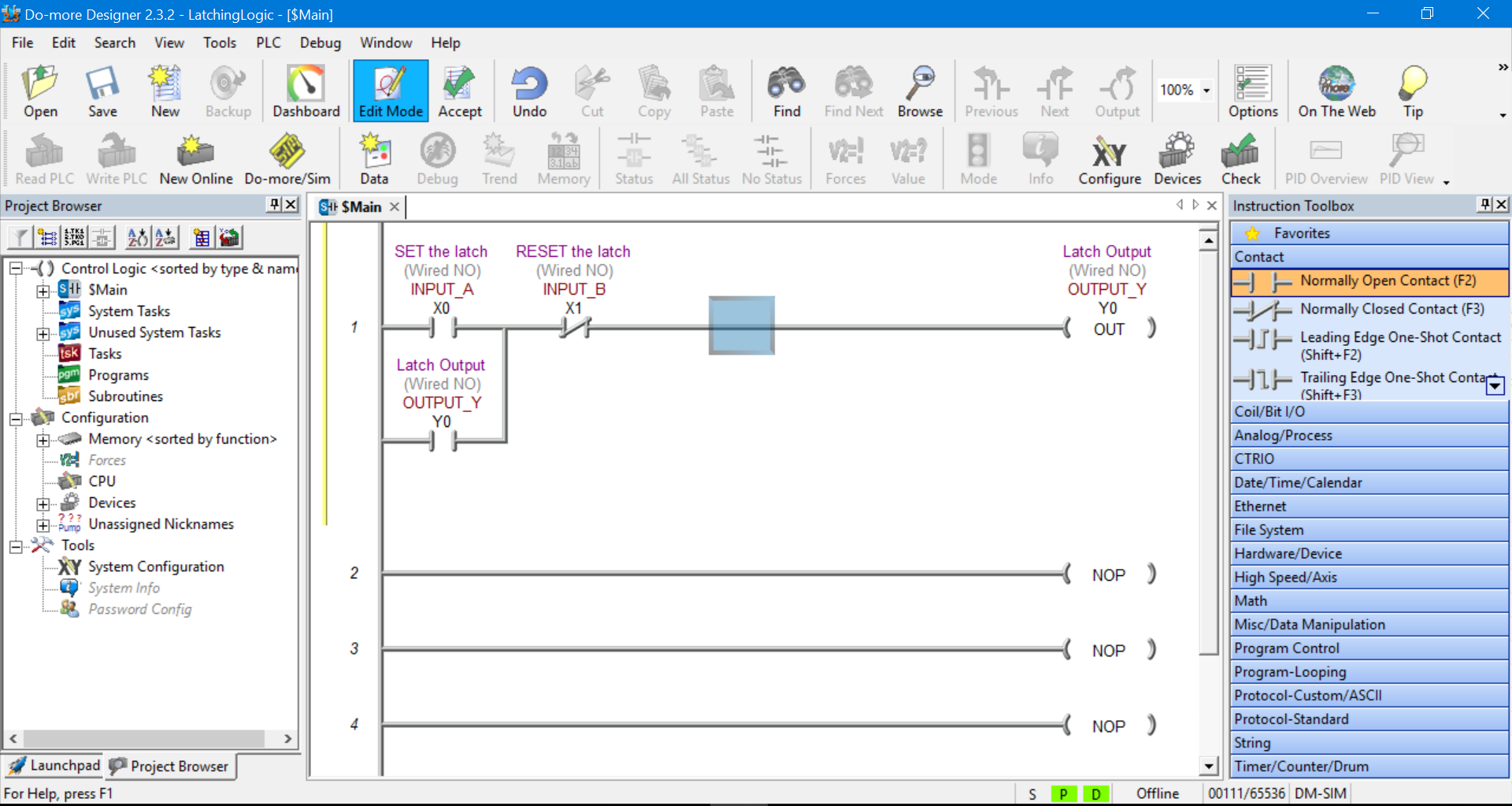
This will create a connection from rung 1 down to the end of Output Y normally open contact. Thus creating a branch (or parallel) connection across INPUT A normally open contact….
The final result should look like this….
Compile the Changes Made to the Ladder Diagram
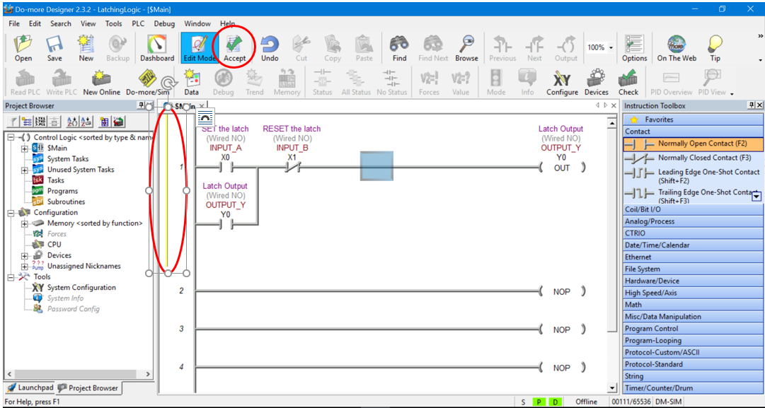
Before we can proceed we need to compile any changes that have been made to the ladder diagram.
The yellow bar on the left hand side of the first rung on the ladder diagram prompts you to compile the programming changes by clicking the Accept button in the Main Toolbar….
After the Accept button is clicked a green bar appears prompting you to save the ladder diagram project.
Click the Save button in the Main Toolbar and if the properties pop up box appears click ok. Once the project is saved the green bar disappears….
Connect to the PLC Simulator
We are now ready to connect to the PLC programming simulator.
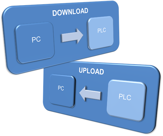
The PLC programming simulator behaves just like a PLC. You need to connect to it, download your program and place it in RUN mode.
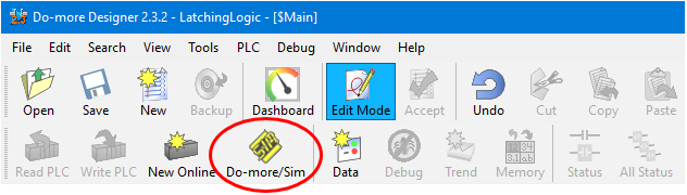
First we need to fire up the PLC simulator by clicking on the Do-more/Sim button on the Main Toolbar….
Click OK when the “Launch and Connect to Do-more PLC Simulator?” pop up appears. The Do-more PLC Simulator will then launch….
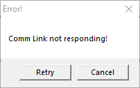
You may have some communication errors pop up. This is because we haven’t connected to the PLC simulator yet.
Please Note….The error popup box may be behind the PLC simulator window. This took a bit to figure out, very sneaky. Hope that saves you some pain!
If you get an error pop up box appear displaying “Comm Link not responding” then click Cancel….
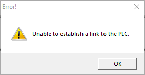
If you get an error pop up box appear “Unable to establish a link to the PLC.” then click OK….
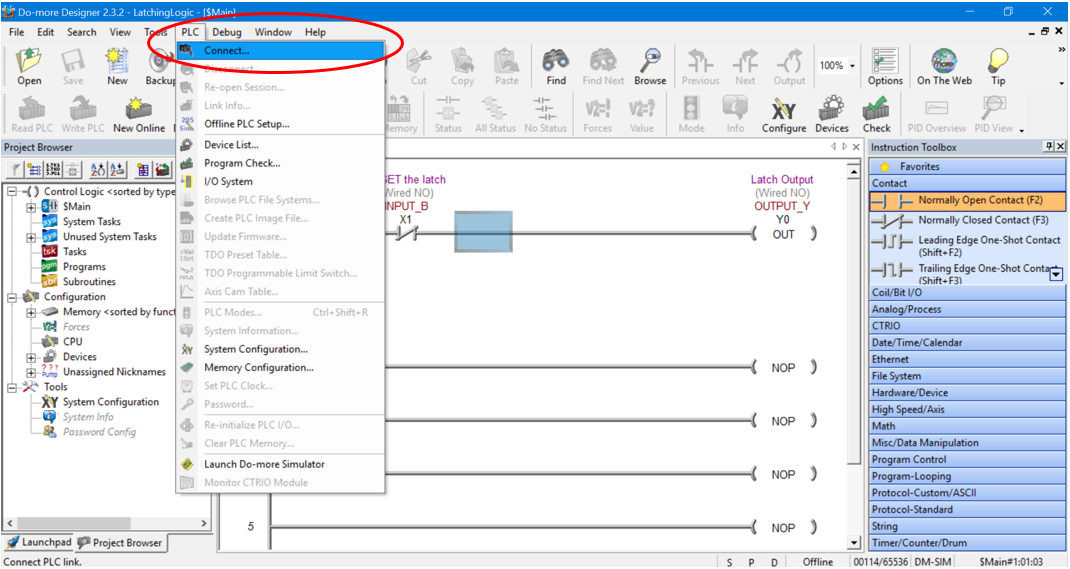
Now, let’s connect to the PLC simulator. Go to the PLC tab in the Main Toolbar and click on Connect….
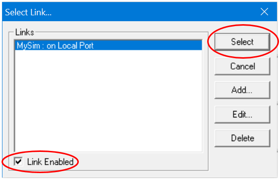
The “Select Link…” pop up box appears with “MySim: on Local Port” highlighted. Make sure to select the “Link Enabled” check box in the bottom left hand corner and then click the Select button….
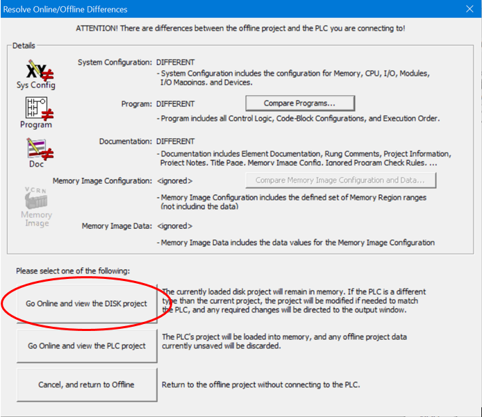
The “Resolve Online/Offline Differences” pop up box appears because we have not downloaded the ladder diagram to the PLC simulator yet. Click on “Go Online and view the DISK project” button….
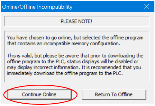
Then click the Continue Online button when the “Online/Offline Incompatibility” pop up box appears….
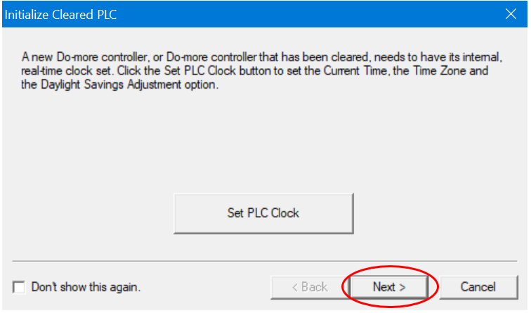
Click the Next button when the “Set PLC Clock” pop up box appears….
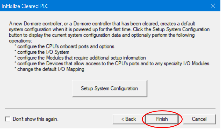
Click the Finish button when the “Setup System Configuration” pop up box appears….
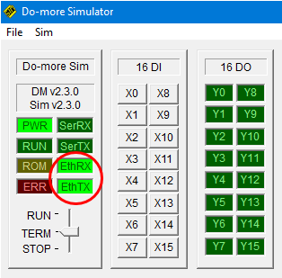
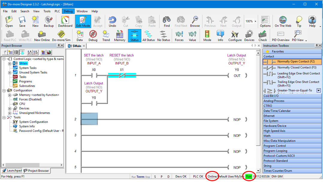
We should now be connected to the PLC simulator. The Status Bar at the bottom of the ladder diagram editor should read Online….

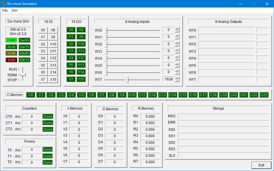
Also, the PLC simulator EthRX and EthTX indication boxes should be green to indicate simulated Ethernet transmit and receive signals between the software and PLC simulator.
If they are flashing then the Status function is turned off, we’ll take care of that a bit later….
Download and Run the PLC Simulator
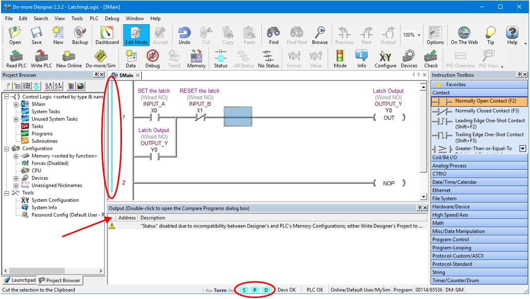
The light blue bar on the left hand side of the first rung on the ladder diagram indicate that there are differences between the offline ladder diagram and online PLC programming simulator.
Also, the S, P and D boxes in the bottom Status Bar are also highlighted light blue to indicate that there are program differences between the offline ladder diagram and online PLC programming simulator.
Lastly, there should be warning message appear just below the rung editing area which is triggered because of the differences between the offline ladder diagram and online PLC simulator …..
All we need to do to now is download the offline ladder diagram to the PLC programming simulator.
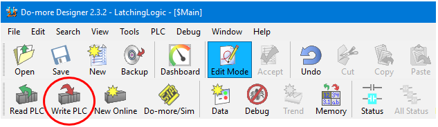
Click on “Write PLC” in Main Toolbar to download the ladder diagram to the PLC simulator….
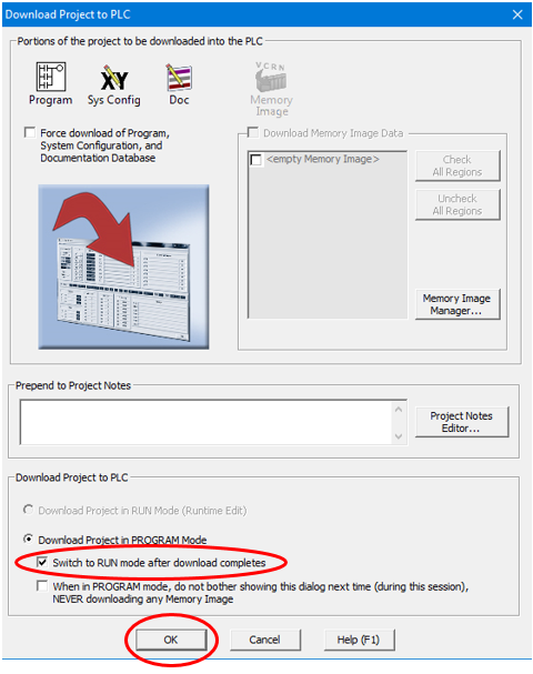
When the “Download Project to PLC” pop up box appears select the check box to “Switch to RUN mode after download completes” and then click OK….
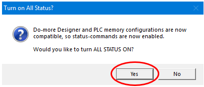
Click Yes to turn ALL STATUS ON….
Now we are connected to the PLC programming simulator, have downloaded the ladder diagram and have turned the Status indication ON.
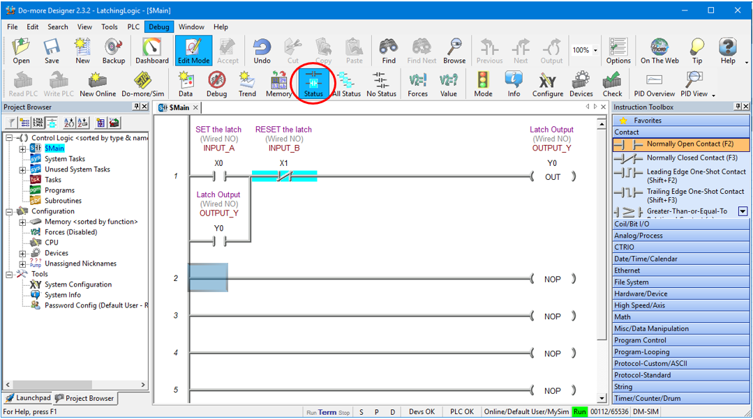
We should have the status bar at the bottom of the ladder diagram editor window displaying Online and Run….
The PLC simulator EthRX and EthTX indication boxes should change to be steady green when the Status indication ON.
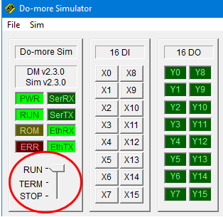
We have already put the PLC simulator into RUN mode when we did the download, but while we are here we can drag and drop the PLC Mode Switch from TERM to RUN….
Now we’re ready to put the PLC simulator through its paces!
Using the PLC Simulator
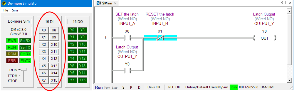
To use the PLC Simulator we just need to click on the input address buttons X0-X15 to change the state of the inputs. When the button is the depressed position the input is ON and when the button is in the released position the input is OFF.
In the ladder diagram the status of the logic symbols highlights in light blue when the ladder symbol logic flow is TRUE.
If the ladder diagram symbols are not highlighting then click on “Status” in Main Toolbar to enable it….
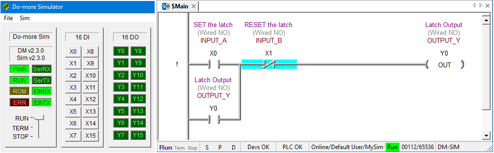
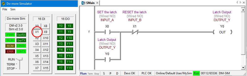
When Inputs X0 and X1 are both de-activated then the logic flow is blocked and Output Y0 is OFF….
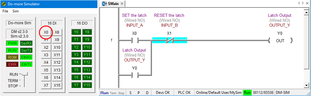
To activate and de-activate inputs we simply click on the X0-15 buttons in the PLC simulator. One click turns the input ON another click turns it OFF….
To SET the latch we must activate Input X0 and de-activated Input X1.
So, Click on the X0 button in the PLC simulator to activate Input X0. Input X1 is already de-activated so we don’t need do anything with it at this stage….
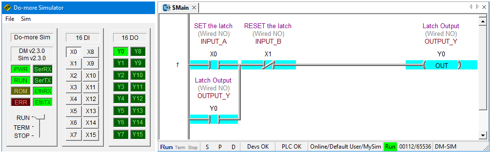
Notice that logic flows through X0 and X1 to output Y0 and they are all highlighted….
Once the latch is SET we can de-activate Input X0 by clicking on the X0 button in the PLC simulator. Notice that Output Y0 is ON and is held in….
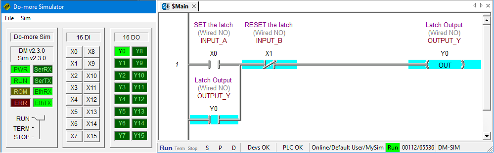
To RESET the latch activate Input X1 by clicking on the X1 button in the PLC simulator.
Because Input X1 is assigned to a normally closed contact symbol logic flow is blocked when the input is activated. That’s opposite to how a normally open contact symbol works and it’s called reverse logic….
To once again SET the latch from this point, Input X1 must be de-activated and then input X0 can be activated.
Adding a Rung Comment Using the Ladder Diagram Editor
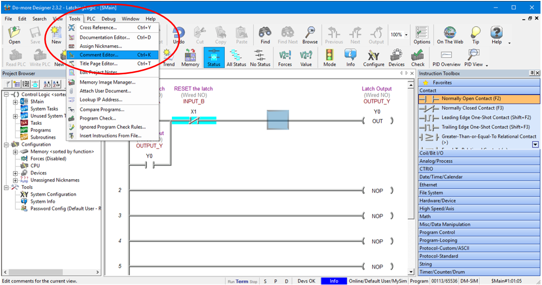
To really start program like a pro let’s add a comment to the rung. First click on rung 1 and in the top toolbar click on Tools and then Comment Editor….
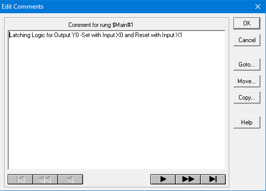
Enter the comments in the dialog box that pops up and hit OK….
Now our ladder diagram should have the comment displayed at the very top of the rung as shown below….
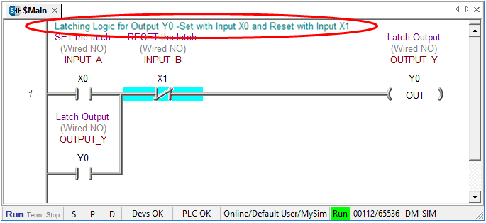
Congratulations…. you have just simulated a PLC latching logic using ladder logic simulator software.
Ladder Logic Simulator Tips
Here are some handy tips to remember…
- Turn Edit Mode on in the Main Toolbar to start programming changes.
- After changing the program click Accept in the Main Toolbar to compile the program.
- Remember to save any programming changes.
- Start the PLC programming simulator before connecting to it.
- When connecting to the PLC make sure to tick the “link Enable” box.
- Put the PLC programming simulator to Terminal mode before downloading.
- To download to your ladder logic to the PLC programming simulator click on the “Write PLC” button in the Main Toolbar.
- Flick the PLC programming simulator to RUN mode to enable logic processing.
- Make sure Status is turned on in the Main Toolbar to see the logic flow indication.
If you are interested in knowing the basics of ladder logic programming then click here.


 Contact")
 Contact")
")
")