PLC timers are frequently used in ladder logic programming. There are many different types of PLC timers, each with their own unique operation and application. Here we will explore some real world PLC timer examples, draw out the ladder diagrams and explain their operation.
A common real world example of using an ON delay timer would be introducing a delayed start to a conveyor and sounding a warning siren before it starts rotating. Another example, using an OFF delay timer, would be to delay a conveyor from stopping allowing it to empty so it is ready for a re-start.
Some ladder logic timer examples that are commonly use while PLC programming are….
ON Delay Timer Example: Delay Start with Warning Siren
ON Delay & OFF Delay Timer Example: Flasher Timer
OFF Delay Timer Example: Delay Stop
Let’s have a look at each one of these examples in a little more detail…
1) ON Delay Timer : Delay Start with Warning Siren
Nowadays most conveyors in factories and mine sites sound a warning siren before they start rotating as a safety precaution for operators and maintenance staff. The siren warns anyone near the conveyor of an imminent start and the delay allows them to get clear of the conveyor as to avoid injury.
A common real world example of using an ON delay timer is to delay the start of a conveyor while sounding a warning siren. The conveyor start command activates the ON delay timer and siren at the same time. After the time delay expires, the siren turns OFF and the conveyor starts running.
With conveyor start warning siren examples we use the ON delay PLC timer to both delay the start of the conveyor and also turn the siren OFF after the delay time expires. We can build on the previous motor control ladder diagram latching example and introduce an ON delay timer to trigger the delayed start and sound the warning siren.
Because we are trying to accomplish two actions (warning siren and motor run) we’ll need to add an intermediate internal variable to replace the M1 RUN output. It’s not essential, it’s just good practice. Maintaining a neat and simple programming structure is important. Otherwise you’ll find your code will become messy, cluttered and hard to follow.
Let’s call the internal variable START COMMAND with address M1.0 (remember, PLC manufacturers use different memory address allocation so M1.0 is an arbitrary address).
Below is the list of inputs required, no change to the previous ladder logic example…..
NAME
ADDRESS
TYPE
COMMENT
PLC WIRING
M1 START
I:1.0
BOOL
Motor No.1 Start Push Button
Normally Open
M1 STOP
I:1.1
BOOL
Motor No.1 Stop Push Button
Normally Closed
M1 TOL
I:1.2
BOOL
Motor No.1 Thermal Overload
Normally Closed
Next let’s add the extra siren output, M1 SIREN…..
NAME
ADDRESS
TYPE
COMMENT
PLC WIRING
M1 RUN
O:1.0
BOOL
Motor No.1 Run
Normally Open
M1 SIREN
O:1.1
BOOL
Motor No.1 Siren
Normally Open
We also need to add an extra internal variable, M1 START COMMAND….
NAME
ADDRESS
TYPE
COMMENT
M1 START COMMAND
M:1.0
BOOL
Motor No.1 Start Command
Finally let’s add the ON delay timer, T1….
NAME
ADDRESS
TYPE
COMMENT
T1
T1
TIMER
Motor No.1 Start Delay Timer
Now we can add the required control logic by using the M1 START COMMAND to trigger each action on a different rung.
Remember…..Both M1 STOP and M1 TOL are wired normally closed (NC) to the PLC inputs to make them “fail safe” and thus need to be configured as normally open (NO) symbols in the ladder diagram.
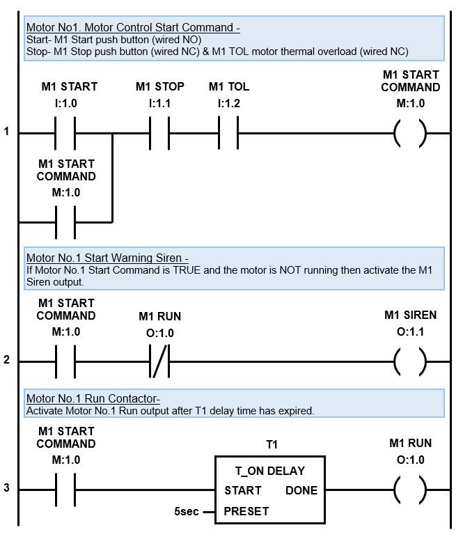
Check out the motor control ladder diagram with delay start warning siren below…
ON Delay PLC Timer Example – Delay Start Warning Siren
The first rung works the same as the standard motor control latching logic previous example. The only difference is we replace the M1 RUN output with an internal variable called M1 START COMMAND. This enables us to use the M1 START COMMAND latch to trigger multiple actions.
After the first rung is scanned it moves to the second rung. If the M1 START COMMAND is TRUE on the first rung and the M1 RUN output is FALSE (motor is not running) then M1 SIREN output is activated.
Please Note – The M1 RUN output symbol is triggered from the third rung.
The scan then jumps to the third rung and if the M1 START COMMAND symbol is TRUE then T1 TON delay timer is activated. After the M1 START COMMAND is TRUE for 5 seconds (preset time) the T1 TON delay timer will activate the M1 RUN output and then Motor No.1 will start running.
That’s not the end of the story, because the siren is still activated. So, when the PLC scan cycles back to the top and moves through the rungs, if the stop inputs have NOT been triggered, the M1 START COMMAND latch will still be active.
So, when the scan gets to the second rung the M1 START COMMAND symbol is still TRUE and the M1 RUN output is also TRUE (the motor is now running). However, the M1 RUN symbol is normally closed (NC), so when it is TRUE, no logic flows and the M1 SIREN output goes FALSE and switches off.
In the first rung, if either the M1 STOP or M1 TOL (thermal overload) inputs are activated, then logic flow is broken in the latching logic and the M1 START COMMAND goes FALSE. This also breaks the logic flow in the second and third rungs resulting in the motor stopping.
If either the M1 STOP or M1 TOL inputs are activated during the five second starting time, while the siren is activated, then the logic flow to the M1 SIREN output is also broken and the siren de-activates.
2) OFF Delay PLC Timer : Delay Stop
The term OFF delay timer naturally implies that there is a delay before something turns off. You know those sensor lights that turn on when you walk into the room and then after you leave they wait awhile before turning off. Right there is one of many everyday examples of an OFF delay PLC timer.
A popular OFF delay timer example using PLC ladder logic is the “delay stop”. My favorite application example is to delay stop a conveyor belt leaving it empty for a no load, trouble free re-start. Another example is to delay stop an electric motor cooling fan to help cool down the motor quicker.
To delay stop an electric motor cooling fan we need to implement an OFF delay timer to start timing after receiving the motor stop signal. To delay stop a conveyor belt and empty it we need to implement the OFF delay timer after the conveyor belt material feeder stops running.
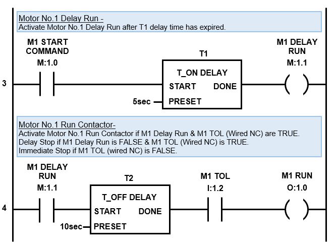
For our OFF delay timer ladder logic example let us build on the previous motor control ladder diagram examples and add an OFF delay PLC timer to create a delay stop using the M1 RUN output. In this example the OFF delay timer is set to 10 seconds.
In this case we would add an OFF delay timer just after the T1 (motor start On delay timer) and before the M1 RUN output. That way the M1 RUN output will activate as soon as the warning siren has finished sounding. And when M1 START COMMAND turns OFF, the Off delay timer will initiate a delay stop with the M1 RUN output.
However, a delay stop is not desired when the motor thermal overload input is triggered. So, in the ladder diagram we must also add the M1 TOL symbol along with the T2 OFF delay timer.
We need to add an extra internal variable and an OFF delay timer to our variable declarations.
Below is the list of required inputs, no change ….
NAME
ADDRESS
TYPE
COMMENT
PLC WIRING
M1 START
I:1.0
BOOL
Motor No.1 Start Push Button
Normally Open
M1 STOP
I:1.1
BOOL
Motor No.1 Stop Push Button
Normally Closed
M1 TOL
I:1.2
BOOL
Motor No.1 Thermal Overload
Normally Closed
Below is the list of required outputs, no change ….
NAME
ADDRESS
TYPE
COMMENT
PLC WIRING
M1 RUN
O:1.0
BOOL
Motor No.1 Run
Normally Open
M1 SIREN
O:1.1
BOOL
Motor No.1 Siren
Normally Open
We need to add an extra internal variable, M1 DELAY RUN, for the delay stop….
NAME
ADDRESS
TYPE
COMMENT
M1 START COMMAND
M:1.0
BOOL
Motor No.1 Start Command
M1 DELAY RUN
M:1.1
BOOL
Motor No.1 Delay Run
Finally let’s add the extra OFF delay timer T2….
NAME
ADDRESS
TYPE
COMMENT
T1
T1
TIMER
Motor No.1 Start Delay Timer
T2
T2
TIMER
Motor No.1 Stop Delay Timer
Check out the PLC Delay Stop timer ladder diagram where we modify the third rung of the previous ladder diagram and then tack on a fourth rung with a TOFF timer to create the delay stop function….
OFF Delay Timer PLC Example: Delay Stop
The third rung works the same as the delay ON timer example above, except we replace the M1 RUN output with internal variable M1 DELAY RUN. This enables us to create a fourth rung and trigger a delay OFF timer in order to create the delay stop.
When the PLC scan hits the third rung it comes across the symbol, M1 START COMMAND . If the motor is running this symbol will be TRUE and the logic will flow to the next symbol, T1 (TON timer for the start siren). Timer T1 starts timing and after 5 second timer T1 DONE output goes TRUE. The logic then flows to M1 DELAY RUN output and it too goes TRUE.
The scan then jumps to the fourth rung where the M1 DELAY RUN symbol is TRUE allowing logic flow to timer T2 (delay OFF timer). When the TOFF timer T2 START input is TRUE its done output also goes TRUE.
The logic then flows to the next symbol M1 TOL input which is TRUE, if the thermal overload input is healthy, and in turn to the M1 RUN output which also goes TRUE. Motor No.1 will start running.
From here the scan will happily cycle through the logic and the motor will continue running until the stop button is pressed. If the M1 STOP input is triggered the logic flow in the first rung will be broken causing M1 START COMMAND output to go FALSE and unlatch.
The scan then moves to the second rung. If the M1 START COMMAND symbol is FALSE it will again break the logic flow, which is of no consequence because the siren is already OFF.
Then the scan will move to the third rung where the M1 START COMMAND symbol is FALSE. This breaks logic flow to both the T1 TON delay timer and M1 DELAY RUN output and they change state to FALSE.
As the scan moves to the fourth rung, M1 DELAY RUN symbol is now FALSE which will break logic flow to T2 timer. When the T2 timer START input changes state to FALSE the timer starts timing.
After 10 seconds has lapsed the timer DONE output changes state from TRUE to FALSE and logic flow is broken to M1 RUN output which also changes to FALSE. Hence, the motor experiences a 10 second delay stop.
Now, if the thermal overload trips, then the motor is overheating and we need an immediate stop. In this case the M1 TOL input, in the first rung, will go FALSE and unlatch the M1 START COMMAND.
When the scan reaches the fourth rung the M1 TOL input will be FALSE which will break the logic flow to M1 RUN output, disabling the delay stop function and causing an immediate motor stop.
3) ON & OFF PLC Timer : Light Flasher.
On and OFF timer logic is often referred to as flasher ladder logic. Why? Because, among other things, we can use it to make a light flash on and off and blink at different rates.
The ON and OFF ladder logic timer is basically a two-step cyclic sequence based on time. Both the ON and OFF times are adjustable. The preset time of the first timer dictates the OFF time and the preset time of the second timer dictates the ON time.
The flashing light PLC timer with two adjustable ON delay timers can be set with an uneven blinking cycle if required. Another timer example with two different cycle times is a plastic shredder that runs cyclically to reduce jamming by going forward for 60 seconds and then reversing for 5 seconds.
A PLC flasher timer utilizes a timer loop in the ladder logic program. Two ON delay timers are programmed in the ladder diagram on consecutive rungs, one after the other. The output of the first timer triggers the second timer, the output of the second timer resets both timers, and the cycle repeats.
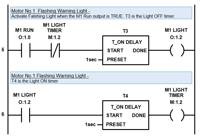
For our flashing light ladder logic example let us build on the previous motor control ladder diagram example and add a flashing warning light that activates after the siren has finished and the motor starts running. In this example the light blinking rate is set to 1 second ON and 1 second OFF.
In this case we would use the M1 RUN output (from the example above) to trigger our timing circuit.
We need to add an extra output, internal variable and two ON delay timers to our variable declarations.
Below is the list of required inputs, no change ….
NAME
ADDRESS
TYPE
COMMENT
PLC WIRING
M1 START
I:1.0
BOOL
Motor No.1 Start Push Button
Normally Open
M1 STOP
I:1.1
BOOL
Motor No.1 Stop Push Button
Normally Closed
M1 TOL
I:1.2
BOOL
Motor No.1 Thermal Overload
Normally Closed
Next let’s add the extra light output, M1 LIGHT….
NAME
ADDRESS
TYPE
COMMENT
PLC WIRING
M1 RUN
O:1.0
BOOL
Motor No.1 Run
Normally Open
M1 SIREN
O:1.1
BOOL
Motor No.1 Siren
Normally Open
M1 LIGHT
O:1.2
BOOL
Motor No.1 Warning Light
Normally Open
We need an extra internal variable for the timers, M1 LIGHT TIMER….
NAME
ADDRESS
TYPE
COMMENT
M1 START COMMAND
M:1.0
BOOL
Motor No.1 Start Command
M1 DELAY RUN
M:1.1
BOOL
Motor No.1 Delay Run
M1 LIGHT TIMER
M:1.2
BOOL
Motor No.1 Warning Light Timer
Finally let’s add the two extra ON delay timers, T3 and T4….
NAME
ADDRESS
TYPE
COMMENT
T1
T1
TIMER
Motor No.1 Start Delay Timer
T2
T2
TIMER
Motor No.1 Stop Delay Timer
T3
T3
TIMER
Motor No.1 Light Flasher Off Timer
T4
T4
TIMER
Motor No.1 Light Flasher On Timer
Check out the PLC ON & OFF timer ladder diagram which we can tack onto the bottom of the previous ladder diagram….
ON & OFF PLC timer examples – Flashing Warning Light
When the PLC scan hits the fifth rung it comes across the M1 RUN output symbol. If the motor is running this symbol will be TRUE and the logic will flow to the next symbol, M1 LIGHT TIMER.
The M1 LIGHT TIMER symbol is normally closed (NC) and will be FALSE because timer T4 (on the sixth rung) is not active and done. This means the M1 LIGHT TIMER symbol allows logic flow to timer T3.
Timer T3 starts timing and after 1 second timer T3 DONE output goes TRUE and the logic flows to M1 LIGHT output and it too goes TRUE.
Then the PLC scan moves to the sixth rung where M1 LIGHT symbol is now TRUE allowing timer T4 to start timing. While timer T4 is timing it’s DONE output is FALSE, therefore the logic flow is broken and M1 LIGHT output is also FALSE.
The scan keeps cycling through the rungs until the 1 second preset time for timer T4 has expired and then timer T4 DONE output on rung six goes TRUE. Then logic flows to M1 LIGHT TIMER output and it too goes TRUE.
When the scan cycles back to the top and moves through to the fifth rung again we notice that M1 LIGHT TIMER symbol has changed state from FALSE to TRUE thus breaking the logic flow and resetting timer T3 and M1 LIGHT output back to FALSE.
As the scan progresses from the fifth to the sixth rung timer the M1 LIGHT symbol at the start of the rung is now FALSE thus breaking the logic flow to the rest of the rung and resetting T4 and M1 LIGHT TIMER output back to a FALSE state as well. Effectively resetting the timer sequence. So when the scan cycles back to the top it starts the timing cycle once again.
The timing cycle will continue until the motor stops running, when the M1 RUN symbol changes state to FALSE.
M1 LIGHT output is used to wire to the flashing light. It will be OFF for T3 time preset (1 second) and ON for T4 timer preset (1 second). The timing cycle will continue until the motor stops running, when the M1 RUN symbol changes state to FALSE.
PLC Timer Examples : Complete Ladder Diagram
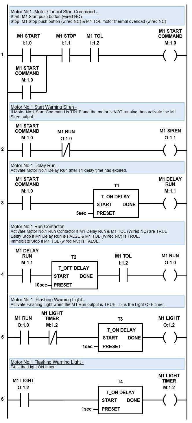
The Delay Start Warning with Siren, Flasher Timer and Delay Stop timer are my 3 favorite timer examples. I frequently use these example in my day to day ladder logic programming. The complete ladder diagram including all three examples for motor start application is below….
PLC Timer Examples – Complete Ladder Diagram
In the next section we’ll discover the four fundamental elements required to structure sequence logic and apply it to automate a real life application.
The PLC timer simulates the function of traditional timer relays. Initially, timer relays were utilized in relay logic circuits and were mechanical in nature. Over time, the mechanical timer relays were replaced by electronic timer relays and now, in modern times, they reside in the PLC as software timers.
A PLC timer is an instruction used in ladder logic programing. When added to a ladder diagram it introduces a time delay when a specific event occurs. In its most basic form a PLC timer has a start input, a preset time input and a done output.
It is important to understand that a PLC timer instruction introduces a time delay which only affects the execution of the timers outputs. The PLC scan is not directly delayed, it still scans through all the ladder logic rungs as per normal.
How does a PLC timer work? A PLC timer continually monitors its start input for a change in its logic state. When the logic state of the start input changes the timer starts running. After the timer reaches the preset time setting, the done output is triggered.
How is a PLC timer reset? Depending on its type, a PLC timer can be reset in one of three ways. ON-delay timers can be reset by removing the start input. OFF-delay timers and Pulse timers are reset after the preset time expires. Other timers, in fact any timer with a reset input, can be reset at any time by triggering the reset input.
Types of PLC Timers
Different types of PLC timers exist based on how they implement the time delay within the timing instruction. The 3 types of PLC timers, as defined in IEC 61131-3 International PLC Programming Standard, are:
ON-Delay Timer (TON)
OFF-Delay Timer (TOF)
Pulse Timer (TP)
In my experience with ladder logic programming I have actually come across 11 different types of PLC timers from various PLC brands, they are:
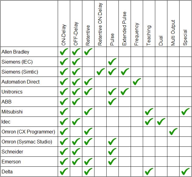
However, not all PLC brands have every timer available for use in their ladder logic programming software. For example some Mitsubishi and Omron PLCs do not have OFF-delay timers. And, as far as I know, the dual timer is unique to Idec PLCs.
Check out the table below which is a comparison of PLC timer instructions that are available in some of the most common PLCs brands….
Comparison of PLC Timer Instructions
Fun Fact… In the table above you’ll notice that there are 2 types of Siemens timers, Simatic and IEC. The Siemens Step7 programming software uses Simatic PLC timers, but the new Siemens TIA Portal programming software has access to both the Simatic timers and the IEC timers.
Application of PLC Timer Types
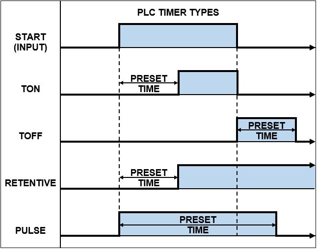
The most common application of PLC timer types are the ON Delay PLC timer, OFF Delay PLC timer, Retentive PLC timer and Pulse PLC timer. Each type uses its time delay and triggers its output in a specific way.
The application of a PLC timer depends on when the time delay is required. If a delay is required after an event changes state to ON, then application of an ON-Delay timer is required. However, if a delay is required after an event changes state to OFF, then application of an OFF-delay timer is required.
Use the chart below to help decide what type of PLC timer to use for your specific application…
PLC Timer Types
PLC Timer Instructions
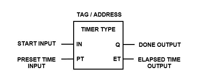
Timer instructions in a PLC have a number of elements which must be defined and/or assigned to an address in order for them to operate correctly. The most common elements that I have come across are shown below….
PLC Timer Type
Tag / Address
Start / Enable (Input)
Preset Time Value (Input)
Time Base (Input)
Reset Input (Input)
Enabled (Output)
Done (Output)
Elapsed / Accumulated Time (Output)
Remaining Time (Output)
The PLC CPU usually has a memory area assigned specifically for PLC timer instructions. Within the PLC ladder logic instruction set, there’s typically support for a limited number of PLC timers. Generally, the larger the PLC CPU memory, the greater the number of available PLC timers.
Timer instructions in a PLC can vary from one PLC brand to another. Things like the PLC timer symbols, tag, addressing, inputs, outputs, count direction (increment/decrement) and time base (usually 1ms, 10ms, 100ms or 1s) can all be different.
Let’s have a look at the different types of PLC timers in a little more detail. We’ll examine all the different PLC timer instructions, their symbols, timing diagrams and operational description from various manufactures and brands. Lets read on….
1) PLC ON Delay Timer
Out of all the different types of PLC timers, the ON delay timer is the one I most commonly use in ladder logic programming. In fact, most of the other timers can be created in ladder logic by using the ON delay timer as the base building block. Luckily most PLCs have created other timing instructions to save us the hassle.
In a PLC the ON delay timer is commonly known as a TON timer. The operation of the ON delay timer is a reflection of its name. You see, the ON Delay Timer (TON Timer) only turns its output ON after a preset time DELAY. In other words, the output is DELAYED before it turns ON.
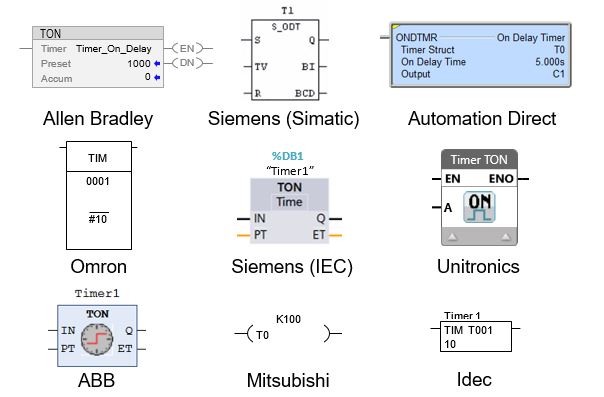
The ON delay timers instruction name, symbol and input/output variables can be expressed in different ways in a ladder logic program depending on which PLC brand you’re using.
For example the TON instruction in a PLC is used in Allen Bradley, Siemens, ABB and Unitronics PLCs. Whereas, the Omron, Mitsubishi, Automation Direct, Delta and Idec PLCs do not use the TON notation for their ON delay timer instruction.
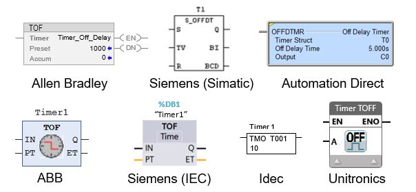
Some examples of ON delay timer instructions, used in different PLC brands, are shown below.…
PLC ON Delay Timer (TON)
How the ON Delay Timer Works
The function of an ON delay timer in a PLC is to monitor the occurrence of a certain event (input), add a time delay and then trigger an action (output) after the time delay expires. The time delay is adjustable (preset time input) and the output is reset when the input turns OFF.
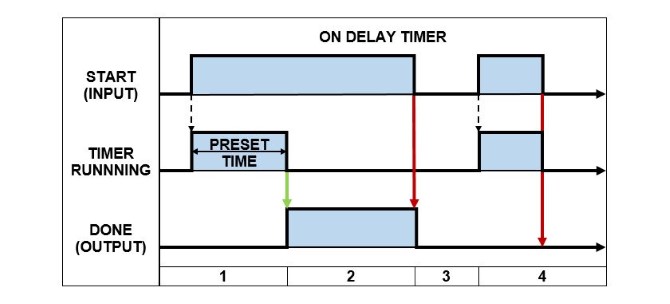
The best way to describe the operation of an ON delay timer is by using a timing diagram like the one below…
PLC ON Delay Timer (TON) – Timing Diagram
Below is the description of how an ON Delay Timer operates in a PLC. The numbers correspond to the PLC ON Delay Timer – timing diagram above…
When the START input changes from FALSE to TRUE the PRESET TIME is loaded and the timer begins running. The DONE output remains FALSE while the timer is running.
After the timer has expired, if the START input is still TRUE, the DONE output is set TRUE.
The DONE output is reset back to FALSE when the START input goes FALSE.
If the START input changes from FALSE to TRUE and then back to FALSE before the timer has expired, the DONE output stays FALSE.
2) PLC OFF Delay Timer
The PLC OFF delay timer is the second most commonly used PLC timer that I use in ladder logic programming, only after the PLC ON delay timer.
In a PLC the OFF delay timer is commonly known as a TOF timer. The operation of the OFF delay timer is a reflection of its name. You see, the OFF Delay Timer (TOF Timer) only turns its output OFF after a preset time DELAY. In other words the output is DELAYED before it turns OFF.
In a ladder logic programming the OFF delay timers instruction name, symbol and input/output variables can actually differ depending on the brand of PLC you’re working with.
For example the TOF instruction in a PLC is used in Allen Bradley, Siemens, ABB, Unitronics, Schneider and Emerson PLCs. Whereas the Automation Direct and Idec PLCs do not use the TOF notation for their OFF delay timer instruction. In fact, the Omron, Mitsubishi and Delta PLCs do not have an OFF delay timer instruction at all.
Some examples of OFF delay timer instructions, used in different PLC brands, are shown below.…
PLC OFF Delay Timer (TOF)
How the OFF Delay Timer Works
The function of an OFF delay timer in a PLC is to monitor the occurrence of a certain event (input) and immediately trigger an action (output). Then, wait for the input to turn OFF, add a time delay and then reset the output. The delay time is adjustable via the preset time input.
What is the basic difference between a TOF and TON delay timer? The TON timer delays the output from turning ON after the input turns ON. Whereas the TOF timer turns the output ON immediately after the input turns ON and delays the output from turning OFF after the input turns OFF.
A great way to describe the operation of an OFF delay timer is by using a timing diagram like the one below…
PLC OFF Delay Timer (TOF) – Timing Diagram
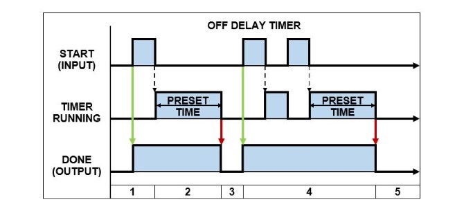
Below is the description of how an OFF Delay Timer operates in a PLC. The numbers correspond to the PLC OFF Delay Timer – timing diagram above…
When the START input changes state from FALSE to TRUE the DONE output is immediately set TRUE.
If the START input changes state from TRUE to FALSE, the PRESET TIME is loaded and the timer begins running.
After the timer expires, the DONE output is reset to FALSE.
If the START input changes state from TRUE and FALSE multiple times, before the timer has expired, the DONE output remains TRUE and the PRESET TIME is re-loaded each time.
After the timer expires, the DONE output is reset to FALSE.
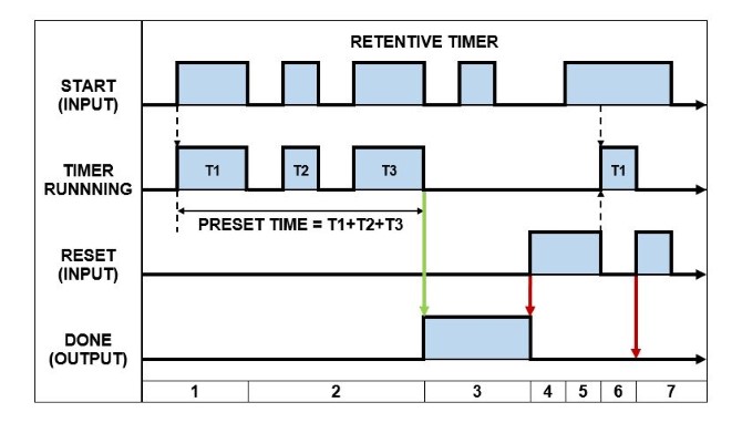
3) PLC Retentive (Accumulating) Timer
The Retentive Timer in a PLC works in a similar fashion to the ON Delay Timer because it delays the output from turning ON. But it has some extra features and subtle differences.
In a PLC the Retentive Timer is commonly known as a RTO timer (Retentive Timer ON). The operation of the Retentive Timer is a reflection of its name. You see, it RETAINS the amount of time that the input is active for and only turns the output ON once the total retained time is equal to the preset time value.
A retentive timer is used to record the amount of time that the input is active for and trigger an output after a preset period of time has been reached. A great example is monitoring the accumulated run time hours of a piece of equipment then triggering an alarm when it is time to be serviced.
What happens when the input of a RTO timer becomes false? When the input of a RTO timer becomes false the timer is paused and the current time value is retained. When the input goes true again, the timer resumes from where it left off. Unlike the ON delay timer, the output is not reset when input of an RTO timer becomes false.
How do you reset RTO timer? After the RTO timer is done the output stays ON and can only be reset by triggering the reset input. The reset input has priority and will reset the timer accumulated value back to 0 and the output to OFF. The RTO timer will restart when the start input is ON and the reset input is OFF.
The name, symbols, and input/output variables for Retentive timers can vary within a ladder logic program based on the specific brand of PLC that you’re utilizing. For example the RTO instruction in a PLC is used in Allen Bradley PLCs. However, Siemens (IEC) use TONR, Mitsubishi use T and GE Fanuc (Emerson) use ONDTR.
The PLC Retentive Timer is also known as an Accumulating Timer in some PLC brands. Some examples of PLCs with accumulating timer instructions are Omron with TTIM, Unitronics with TA, Automation Direct with TMRA instruction. Whether the terminology used is retentive timer or accumulating timer their operation is essentially the same.
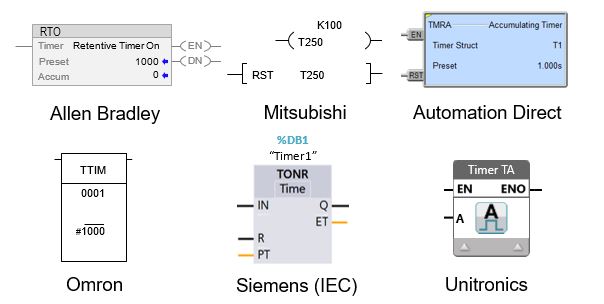
Some examples of Retentive timer instructions, used in different PLC brands, are shown below.…
PLC Retentive (Accumulating) Timer
How the Retentive Timer Works
The function of a Retentive timer in a PLC is to monitor the occurrence of a certain event (input), record the amount of time that the input is ON and turn the output ON after the accumulated time reaches the preset time value. The retentive timer can only be restarted by triggering the reset input.
An awesome way to describe the operation of a Retentive timer is by using a timing diagram like the one below…
PLC Retentive Timer – Timing Diagram
Below is the description of how a Retentive Timer operates in a PLC. The numbers correspond to the PLC Retentive Timer – timing diagram above…
When the START input changes from FALSE to TRUE and the RESET input is FALSE, the timer PRESET VALUE is loaded and the timer starts running. The DONE output is FALSE at this stage.
When the START input goes FALSE the timer is stopped, but the accumulated time is retained. When the START input is set TRUE again, the timer resumes running from its last accumulated value, but the DONE output does not change state.
After the PRESET TIME expires, the DONE output is then set TRUE. Under this condition, if the START input changes state, the DONE output is unaffected.
When the RESET input goes TRUE, the DONE output is reset to FALSE.
If the START input and RESET input are TRUE at the same time, the RESET input has priority. Therefore, the DONE output is reset to FALSE and the timer is stopped.
If the START output is TRUE and the RESET input is FALSE, the PRESET TIME is loaded and the timer begins running.
If the RESET input is set TRUE, regardless of the state of the START input or timer status, the DONE output is reset to FALSE and the timer is stopped.
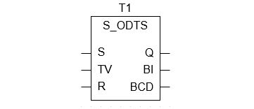
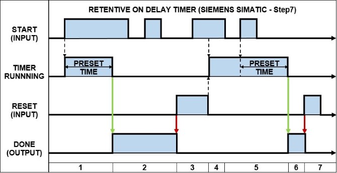
4) Retentive ON Delay Timer (Siemens PLC)
The Retentive ON Delay Timer is unique to the Siemens PLC. In the Siemens PLC the Retentive ON Delay Timer is known as S_ONDTS timer (Retentive ON Delay S5 Timer).
The operation of the Retentive ON Delay Timer (S_ONDTS) is similar to the ON Delay Timer because it only turns its output ON after a preset time DELAY. However, the output can only be reset by triggering the reset input and if the start input is re-triggered, while the timer is running, the timer restarts.
It’s kinda like blending the ON delay and Retentive timers together.
The S_ONDTS timer delays the output from turning ON, but unlike the Retentive timer, does not retain (accumulate) the timer value. Instead it restarts the timer. And unlike the ON delay timer it does not reset when the start input turns OFF. Instead the reset input must be triggered.
In my opinion it should have been called an “ON Delay Extended Timer”.
The Retentive ON Delay Timer instruction is expressed in the Siemens PLC as per below….
Siemens PLC Retentive ON Delay Timer (S_ODTS)
How the Retentive ON Delay Works
The function of a Retentive ON Delay Timer in a Siemens PLC is to monitor the occurrence of a certain event (input), add a time delay to it, trigger an action (output) and keep the output ON even if the input turns OFF (aha – the output is “retentive”). The output is only reset by triggering the reset input.
A fantastic way to describe the operation of a Retentive ON Delay Timer in a Siemens PLC is by using a timing diagram like the one below…
Siemens Retentive ON Delay Timer (S_ODTS) – Timing Diagram
Below is the description of how a Retentive ON Delay Timer operates in a Siemens PLC. The numbers correspond to the PLC Retentive ON Delay Timer (S_ODTS) – timing diagram above…
When the START input changes from FALSE to TRUE and the RESET input is FALSE, the PRESET TIME is loaded and the timer begins running. The DONE output remains FALSE while the timer is running.
After the timer has expired, the DONE output is set to TRUE, regardless of the state of the START input.
When the RESET input goes TRUE, the DONE output is reset to FALSE. If the START input and RESET input are TRUE at the same time, the RESET input has priority. Therefore, the DONE output is reset to FALSE.
When the START input is TRUE and the RESET input is FALSE, the PRESET TIME is loaded and the timer begins running.
If the START input transitions from TRUE to FALSE, while the timer is running, the timer is unaffected and keeps running. But if the START input transitions from FALSE to TRUE, while the timer is running, the PRESET TIME is re-loaded and the timer re-starts.
After the timer has expired, the DONE output is set to TRUE, regardless of the state of the START input.
The DONE output is reset back to FALSE by setting the RESET input to TRUE.
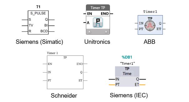
5) PLC Pulse Timer
The PLC Pulse Timer is another common timer found in PLC programming. It is one of the three PLC timers defined in IEC 61131-3 International PLC Programming Standard.
In a PLC the Pulse Timer is commonly known as a PT timer. The Pulse Timer creates an output PULSE with a pulse duration equal to that of the preset time value. In simple terms, the TP timer output is ON when the timer is running and is OFF all other times.
In a ladder logic programming the Pulse timers instruction name, symbol, and input/output variables can differ based on the brand of PLC you’re using.
For example the TP timer instruction in a PLC is used in Siemens (IEC), Unitronics, Schneider, ABB and Emerson PLCs. However, Siemens PLCs (Simatic) use the S_PULSE instruction instead. Some PLC brands such as Allen Bradley, Automation Direct,
Mitsubishi, Omron (CX Programmer) and Idec do not have a pulse timer instruction at all.
Some examples of Pulse timer instructions, used in different PLC brands, are shown below.…
PLC Pulse Timer
How the Pulse Timer Works
How does a pulse timer work? A PLC pulse timer begins to work when its input changes state from FALSE to TRUE. The output is turned ON and the timer starts counting. When the preset time expires the output is turned OFF. Thus, a pulse is created which has a duration equal to that of the timers preset time value.
What is the output of a PLC TP timer? The PLC TP timer output generates a pulse that has a specific time duration. The TP timer output is usually expressed as the letter “Q”. The output of the TP timer is set TRUE when its input changes state to TRUE and its output will stay TRUE until the preset time expires, regardless of the state its input.
A magnificent way to describe the operation of a TP Pulse timer is by using a timing diagram like the one below…
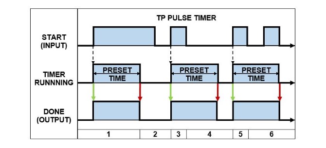
PLC Pulse Timer (TP) – Timing Diagram
Below is the description of how a TP Pulse Timer operates in a PLC. The numbers correspond to the PLC Pulse Timer (TP) – timing diagram above…
When the START input changes from FALSE to TRUE the PRESET TIME is loaded and the timer begins running. The DONE output is set to TRUE.
If the timer expires while the START input is TRUE then the DONE output is reset to FALSE.
When the START input changes from FALSE to TRUE the PRESET TIME is loaded and the timer begins running. The DONE output is set to TRUE.
If the START input is reset to FALSE the timer keeps running. When the timer expires the DONE output is reset to FALSE.
When the START input changes from FALSE to TRUE the PRESET TIME is loaded and the timer begins running. The DONE output is set to TRUE.
If the START input transitions from TRUE to FALSE, while the timer is running, the timer is unaffected and keeps running. When the timer expires the DONE output is reset to FALSE.
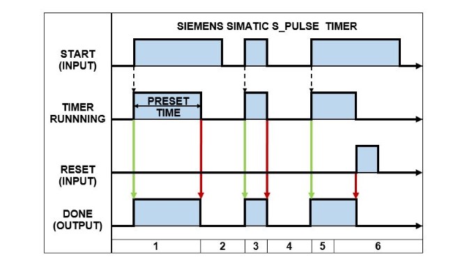
How the Siemens SIMATIC Pulse Timer Works
The Siemens Simatic Pulse timer (S_PULSE) operates slightly differently compared to the TP pulse timer. You see, the Siemens Simatic Pulse timer resets the DONE output when the START input transitions from TRUE to FALSE. Whereas, the TP Pulse timer reset the DONE output after the preset time expires.
Check out the operation of a S_PULSE timer in a Siemens Simatic PLC using the timing diagram below…
Siemens (S_PULSE) Timer – Timing Diagram
Below is the description of how a S_PULSE Timer operates in a Siemens Simatic PLC. The numbers correspond to the PLC Pulse Timer – timing diagram above…
When the START input changes from FALSE to TRUE the PRESET TIME is loaded and the timer begins running. The DONE output is set to TRUE.
If the timer expires while the START input is TRUE then the DONE output is reset to FALSE.
When the START input changes from FALSE to TRUE the PRESET TIME is loaded and the timer begins running. The DONE output is set to TRUE.
If the START input is reset to FALSE then the DONE output is also reset to FALSE.
When the START input changes from FALSE to TRUE the PRESET TIME is loaded and the timer begins running. The DONE output is set to TRUE.
If the RESET input changes from FALSE to TRUE, the timer is stopped and the DONE output is reset to FALSE. After the RESET input has been triggered the timer can only be restarted if the RESET input is FALSE and the START input changes from FALSE to TRUE (Section 1).
6) PLC Extended Pulse Timer
The PLC Extended Pulse Timer operates in a very similar way to the Pulse Timer. However, as its name suggests, the Extended Pulse timer has an extended feature.
The Extended Pulse Timer (TE timer) creates an output PULSE with a pulse duration equal to that of the preset time value, just like the Pulse Timer. Additionally, the output pulse is EXTENDED if the input is re-triggered before the timer expires.
What is the difference between a Pulse Timer and Extended Pulse timer in a PLC? The PLC Pulse timer, once triggered, has a pulse duration equal to the preset time regardless of the input state. Whereas, the Extended Pulse timer restarts its timer every time the input is re-triggered, thus extending the pulse duration.
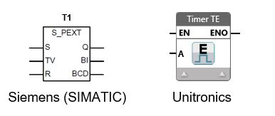
In my experience I’ve only come across Extended Pulse timers in Siemens PLCs and Unitronics PLCs. The Siemens SIMATIC PLC Extended Pulse timer instruction is known as a S_PEXT timer. While the Unitronics PLC Extended Pulse timer is known as a TE timer.
The Siemens SIMATIC PLC Extended Pulse timer (S_PEXT) and Unitronics PLC Extended Pulse timer (TE) instructions are shown below.…
PLC Extended Pulse Timer
How the Extended Pulse Timer Works
The Siemens PLC extended pulse timer uses the instruction name S_PEXT. While the Unitronics PLC extended pulse timer uses the instruction name TE. Even though these extended pulse timer have different instruction names their operation is essential the same.
A spectacular way to describe the operation of an Extended Pulse timer is by using a timing diagram like the one below…
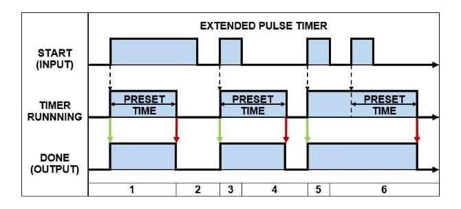
PLC Extended Pulse Timing Diagram
Below is the description of how an Extended Pulse Timer operates in a PLC. The numbers correspond to the PLC Extended Pulse Timer – timing diagram above…
When the START input changes from FALSE to TRUE the PRESET TIME is loaded and the timer begins running. The DONE output is set to TRUE.
If the timer expires while the START input is TRUE then the DONE output is reset to FALSE.
When the START input changes from FALSE to TRUE the PRESET TIME is loaded and the timer begins running. The DONE output is set to TRUE.
If the START input is reset to FALSE the timer keeps running. When the timer expires the DONE output is reset to FALSE.
When the START input changes from FALSE to TRUE the PRESET TIME is loaded and the timer begins running. The DONE output is set to TRUE.
If the START input transitions from TRUE to FALSE, while the timer is running, the timer is restarted. When the timer expires the DONE output is reset to FALSE.
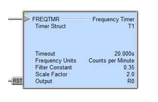
7) PLC Frequency Timer
As far as I know, the Frequency timer is unique to the Automation Direct PLC. It works differently to other timers because it doesn’t introduce a time delay. In fact, I think it’s more like a frequency counter as opposed to a PLC timer.
In an Automation Direct PLC the Frequency timer is referred to as the FREQTMR instruction. The operation of the Frequency timer is a reflection of its name. Simply put, it measures the time between input pulses and converts it to a frequency value.
The frequency timer has a number of settings that enable it to be implemented to convert a pulsed input into the desired engineering units like speed or flow rate. These settings are:
Frequency Time base in seconds, minutes or hours
Filter for data smoothing
Scaling factor
Output as a REAL (floating point) variable
An example of a Frequency timer (FREQTMR) instruction used in an Automation Direct PLC is shown below.…
Automation Direct Frequency Timer (FREQTMR)
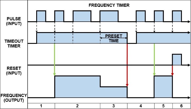
How the Frequency Timer Works
The function of a Frequency timer in an Automation Direct PLC is to monitor the occurrence of a certain event (input), measure the time between successive events and then convert the value to engineering units based on the time base, filter and scaling settings.
The Frequency timer output value can be reset in one of 2 ways:
The reset input is set ON.
The time between input pulses is longer than the Timeout setting.
An outstanding way to describe the operation of a Frequency timer in an Automation Direct PLC is by using a timing diagram like the one below…
Automation Direct Frequency Timer (FREQTMR) – Timing Diagram
Below is the description of how a Frequency timer operates in an Automation Direct PLC. The numbers correspond to the Automation Direct PLC Frequency Timer (FREQTMR) – Timing Diagram above…
When the PULSE input changes from FALSE to TRUE (positive edge signal) the TIMEOUT preset time is loaded and the TIMEOUT timer starts running.
Initially, after two consecutive positive edge signals at the PULSE input the FREQUENCY output is calculated and its value set. The TIMEOUT preset time is reloaded each time there is a positive edge signal at the PULSE input.
If the TIMEOUT timer expires before a positive edge signal at the PULSE input, the FREQUENCY output value is set to zero.
When the PULSE input changes from FALSE to TRUE (positive edge signal) the TIMEOUT preset time is loaded and the TIMEOUT timer starts running.
Initially, after two consecutive positive edge signals at the PULSE input the FREQUENCY output is calculated and its value set. The TIMEOUT preset time is reloaded each time there is a positive edge signal at the PULSE input.
If the RESET input is set to TRUE the FREQUENCY output value is reset to zero.
8) PLC Teaching Timer
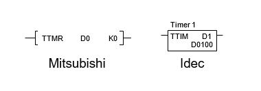
The Teaching timer is not a very common timer at all. In fact, I’ve only seen it in used in Mitsubishi PLCs and Idec PLCs. The Teaching timer doesn’t actually apply a time delay, but rather measures the time. Let’s check it out…
The Teaching timer is referred to as the TTMR instruction in the Mitsubishi PLC, while in the Idec PLC, the Teaching timer is referred to as the TTIM instruction. The Teaching timer works by monitoring the status of its input and storing the input ON duration time value in the allocated PLC data register.
A teaching timer is used to record the amount of time that the timers input is active for and store the recorded time in the PLC memory. The stored time value, recorded by the Teaching timer, can be scaled and used in other parts of the ladder logic program, like the preset time of a time instruction.
The difference between the Mitsubishi PLC and Idec PLC Teaching timers is one minor detail. The Mitsubishi PLC has an additional scaling factor that is applied as part of its teaching timer instruction. After the input ON duration has been measured the scaling factor is applied and then the result is stored.
The Mitsubishi PLC Teaching timer (TTMR) and Idec PLC Teaching timer (TTIM) instructions are shown below.…
PLC Teaching Timer
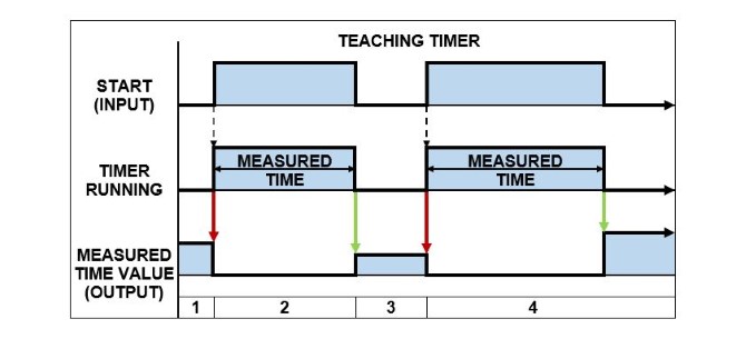
How the Teaching Timer Works
The function of a Teaching timer in a PLC is to monitor the occurrence of an event (input), record the time that the input is ON and store the value in the PLC memory. The teaching timer is restarted when the input transitions from OFF to ON and the value is stored when the input transitions from ON to OFF.
A phenomenal way to describe the operation of a Teaching timer is by using a timing diagram like the one below….
PLC Teaching Timer – Timing Diagram
Below is the description of how a Teaching Timer operates in a PLC. The numbers correspond to the PLC Teaching Timer – timing diagram above…
When the START input changes from FALSE to TRUE, the timer starts running and the last stored measured time value (output) is reset.
When the START input changes from TRUE to FALSE the timer is stopped and the measured time value (output) is stored in the PLC memory.
While the START input is FALSE, the measured time value (output) is retained in the PLC memory.
Same as 1), 2) &3). Please note: the measured time value (output) increases in proportion to the time the start input is TRUE.
9) PLC Dual Timer
The Dual timer is another timer that is not commonly found in PLCs. In fact, I’ve only seen it used in Idec PLCs. The Dual timer has two timers built into the one instruction. These timers work together to create a pulsed output. Let’s take a closer look.…
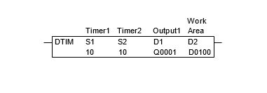
The Dual timer is commonly referred to as the DTIM instruction in the Idec PLC. It has two built in timers which are used to generate a pulsed output whenever the status of its input is ON. The ON and OFF duration of the output pulse is set using the preset time inputs.
The Dual timer has a number of settings that enable it to be create a pulsed output. These settings are:
S1 – Preset Time Input 1
S2 – Preset Time Input 2
D1 – Timer Done Output
D2 – System Work Area (2x Data Registers)
As with other Idec PLC timers, there are multiple instruction names for the Dual timer depending on the time base value. So if the preset time value is 10 and the time base is 100ms, then the actual timer value is 10 x 100ms = 1000ms, or 1sec. Here are the Dual timer instructions and their respective time base values….
DTML = 1 s time base
DTIM = 100 ms time base
DTMH = 10 ms time base
DTMS = 1 ms time base
An example of an Idec PLC Dual timer (DTIM timer) instruction is shown below. It has a time base of 100ms with both S1 and S2 preset time values equal to 10. So it has a 1 second ON and 1 second OFF pulse output.…
IDEC Dual Timer
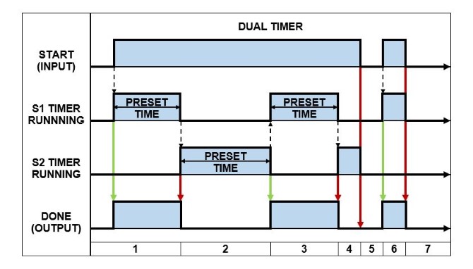
How the Dual Timer Works
The function of a Dual timer in an Idec PLC is to monitor the status of the timer input and generate a pulsed output according to the preset time values. The output pulse generated by the Dual timer is active as long as the status of the timer input is ON.
A splendid way to describe the operation of a Dual timer in an Idec PLC is by using a timing diagram like the one below….
IDEC Dual Timer – Timing Diagram
Below is the description of how a Dual Timer operates in a PLC. The numbers correspond to the IDEC Dual Timer – timing diagram above….
When the START input changes from FALSE to TRUE the S1 PRESET TIME is loaded and the S1 timer begins running. The DONE output is set to TRUE.
After the S1 timer expires, the DONE output is reset to FALSE. The S2 PRESET TIME is loaded and the S2 timer begins running.
After the S2 timer expires, the DONE output is set to TRUE. The S1 PRESET TIME is loaded and the S1 timer begins running.
After the S1 timer expires, the DONE output is reset to FALSE. The S2 PRESET TIME is loaded and the S2 timer begins running.
If the START input transitions from TRUE to FALSE, while the timers are running, the timers are stopped and the DONE output is reset to FALSE.
When the START input changes from FALSE to TRUE the S1 PRESET TIME is loaded and the S1 timer begins running. The DONE output is set to TRUE.
If the START input transitions from TRUE to FALSE, while the timers are running, the timers are stopped and the DONE output is reset to FALSE.
The Dual timer in an Idec PLC creates a pulsed output with a single instruction. However, in other PLCs a timed pulsing output must be created with ladder logic using 2x ON delay timer instruction. The functionality of 2 timers is built into the Dual timer instruction.
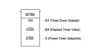
10) PLC Multi Output Timer
The Multi Output timer is yet another not-so-common timer. It uses a single timer, with multiple preset time values and multiple outputs. This “beast of a timer” is only found in some Omron PLCs.
In an Omron PLC the Multi Output timer is referred to as the MTIM instruction. It has eight independent done outputs each with their own preset time input. The Multi Output timer works just like an ON Delay timer (TON Timer). Each output is delayed from turning on by its corresponding preset time value.
Multi Output timer has a number of settings that enable it produce multiple done outputs. These settings are:
D1 – Timer Done Outputs.
D2 – Elapsed Time Output.
S – Preset Time Inputs.
D1 contains the 8 Timer Done Output bits. It uses bit 0-7 for the Timer Done Outputs, bit 8 for Reset and bit 9 for Pause. Bits 10-15 are not used.
D1 – Bit0: Timer Done Output 1.
D1 – Bit1: Timer Done Output 2.
D1 – Bit2: Timer Done Output 3.
D1 – Bit3: Timer Done Output 4.
D1 – Bit4: Timer Done Output 5.
D1 – Bit5: Timer Done Output 6.
D1 – Bit6: Timer Done Output 7.
D1 – Bit7: Timer Done Output 8.
D1 – Bit8: Reset Input.
D1 – Bit9: Pause Input.
D2 contains the elapsed timer value.
S1 is assigned to the Preset Time Input 1, which acts as an address pointer. An address offset is used to allocate a separate Preset Time Input for each timer output. See below:
S1+0: Preset Time Input 1.
S1+1: Preset Time Input 2.
S1+2: Preset Time Input 3.
S1+3: Preset Time Input 4.
S1+4: Preset Time Input 5.
S1+5: Preset Time Input 6.
S1+6: Preset Time Input 7.
S1+7: Preset Time Input 8.
An example of an Omron PLC Multi Output timer (MTIM) instruction is shown below….
Omron PLC Multi Output Timer
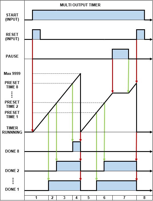
How the Multi Output Timer Works
The function of a Multi Output timer in an Omron PLC is to monitor the status of the timer input and generates eight done output bits according to the preset time values. All eight timer done outputs are generated independently and are based their own separate preset time values.
The MTIM instruction has a time base of 100ms with a max preset time value of 999.9 seconds. If a preset time value is set to 0 then all subsequent preset time values are ignored. The reset bit sets the elapsed timer value back to zero and the timer done output bits to FALSE.
An amazing way to describe the operation of a Multi Output timer in an Omron PLC is by using a timing diagram like the one below….
Omron Multi Output Timer – Timing Diagram
Below is the description of how a Multi Output Timer operates in an Omron PLC. The numbers correspond to the Omron PLC Multi Output Timer – timing diagram above…
When the START input changes from FALSE to TRUE and the RESET input is triggered all the DONE output bits are reset to FALSE and the timer is restarted.
The timer counts up and when PRESET TIME 1 value is reached the DONE 1 output is set TRUE.
The timer continues to count up and when PRESET TIME 2 value is reached the DONE 2 output is set TRUE.
The timer continues to count up and as each PRESET TIME value is reached the corresponding DONE output is set true up to PRESTE TIME 8 where DONE 8 output is set TRUE.
Once the timer reaches the max value of 9999 the timer restarts and all DONE outputs are reset to FALSE.
The timer continues to count up and when PRESET TIME 1 & 2 values are reached the corresponding DONE outputs are set TRUE.
When the PAUSE input changes from FALSE to TRUE the timer stops counting up and the DONE outputs do not change state. After the PAUSE input resets back to FALSE the timer continues to count up.
If the RESET input is triggered and the START input is reset to FALSE, all the DONE outputs are also reset to FALSE and the timer is reset and stopped
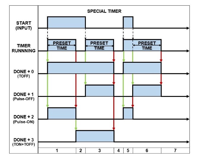
11) PLC Special Timer
I’ve saved “the best” PLC timer instruction for last. It’s called the Special timer. It certainly is “special”. I’ve only ever seen the Special timer used in Mitsubishi and Delta PLCs. This sucker has four separate timer functions built into the one PLC instruction. What a monster! Let’s take a closer look.…
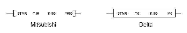
The Special timer is commonly referred to as the STMR instruction in the Mitsubishi and Delta PLCs. The Special timer uses only one timer and one PRESET TIME input. But has four separate timer instructions built into it, each with their own DONE output.
The four types of timer functions contained in the Special timer are the OFF delay timer, Pulse timer (OFF), Pulse timer (ON) and a combined ON delay + OFF delay timer.
The four timer functions of the Special timer are assigned to the DONE output (D) which acts as an address pointer. An address offset is used to allocate a separate DONE output bits for each timer output. See below….
D+0: OFF delay timer.
D+1: Pulse timer (OFF).
D+2: Pulse timer (ON).
D+3: Combined ON delay timer + OFF delay timer.
Examples of the Mitsubishi PLC and Delta PLC Special timer (STMR timer) instructions are shown below….
Mitsubishi & Delta PLC Special Timer
How the Special Timer Works
The function of a Special timer in the Mitsubishi and Delta PLCs is to monitor the status of the timer input and generate the four types of timer done outputs according to the preset time values. All four timer done outputs are based on a single preset time value and are generated separately.
An awe-inspiring way to describe the operation of a Special timer in a Mitsubishi and Delta PLC is by using a timing diagram like the one below….
Mitsubishi & Delta PLC Special Timer – Timing Diagram
Below is the description of how a Special Timer operates in a PLC. The numbers correspond to the Mitsubishi & Delta PLC Special Timer – timing diagram above…
When the START input changes from FALSE to TRUE the PRESET TIME is loaded, the timer begins running and :
D+0 output (TOFF) is set to TRUE.
D+1 output (Pulse-OFF) is reset to FALSE.
D+2 output (Pulse-ON) is set to TRUE.
D+3 output (TON+TOFF) is reset to FALSE.
If the timer expires, while the START input is TRUE, then :
D+0 output (TOFF) remains TRUE.
D+1 output (Pulse-OFF) remains FALSE.
D+2 output (Pulse-ON) is reset to FALSE.
D+3 output (TON+TOFF) is set to TRUE.
After the preset time has expired and the START input is reset to FALSE, the PRESET TIME is loaded, the timer begins running and :
D+0 output (TOFF) remains TRUE.
D+1 output (Pulse-OFF) is set to TRUE.
D+2 output (Pulse-ON) remains FALSE.
D+3 output (TON+TOFF) is remains TRUE.
If the timer expires, while the START input is FALSE, then :
D+0 output (TOFF) is reset to FALSE.
D+1 output (Pulse-OFF) is reset to FALSE.
D+2 output (Pulse-ON) remains FALSE.
D+3 output (TON+TOFF) is reset to FALSE.
When the START input changes from FALSE to TRUE the PRESET TIME is loaded and the timer begins running :
D+0 output (TOFF) is set to TRUE.
D+1 output (Pulse-OFF) is reset to FALSE.
D+2 output (Pulse-ON) is set TRUE.
D+3 output (TON+TOFF) is reset to FALSE.
If the START input changes from TRUE back to FALSE, before the timer gets a chance to expire, then the PRESET TIME is loaded and the timer restarts :
D+0 output (TOFF) remains TRUE.
D+1 output (Pulse-OFF) is set to TRUE.
D+2 output (Pulse-ON) is reset to FALSE.
D+3 output (TON+TOFF) remains FALSE.
If the START input remains FALSE and the timer expires, then :
D+0 output (TOFF) is reset to FALSE.
D+1 output (Pulse-OFF) is reset to FALSE.
D+2 output (Pulse-ON) remains FALSE.
D+3 output (TON+TOFF) remains FALSE.
WOW, that’s a lot of PLC timers to swallow in one hit. If you’ve made it this far, give yourself a rather long “pat on the back”…. WELL DONE TO YOU!
What I’ve found, when using timers while ladder logic programming a PLC, is that I mainly use TON (Delay ON) and TOFF (Delay OFF) timers. Occasionally I will have the need to use some of the other types of timers.
In the next section there are some juicy must have PLC timer examples. Click here to go to the next section.
Experience tells us that once a piece of ladder logic is created that accomplished a specific task it can be re-used in other areas of the program and in other applications as well. So by creating ladder logic programming examples we can speed up or overall programming time.
Constructing a program is then a simple matter of grabbing the appropriate ladder logic programming examples and connecting them in an orderly fashion.
Let’s take a look at some very simple, but extremely important ladder logic programming examples…
Latching in a PLC
Latching is one of the most important pieces of ladder logic programming that you’ll ever use.
Latching in a PLC refers to ladder logic code that simulates the operation of a latching relay. It requires two inputs and an output. The output is latched (set TRUE) with one of the inputs. The output is unlatched (reset to FALSE) with the other input. A momentary pulse can be used for the inputs.
This can be achieved with two methods….
Set and Reset instructions: In an Allen Bradley PLC they are called Latch and Unlatch instructions. These instructions simulate the function of an electro-mechanical latching relay. Advantages include flexibility in programming because the Set (Latch) and Reset (Unlatch) symbols do not need to be in the same rung. The disadvantage is that debugging can become more difficult because the Set (Latch) and Reset (Unlatch) symbols may be scattered throughout the program.
Latching logic: Quite often “latching logic” is referred to as “hold in logic”. It’s ok to interchange the terms. The advantage of latching logic is that troubleshooting is easier because the symbols used are all in the same rung. The disadvantage is that there is some inflexibility in programming because latching logic requires all the symbols to be on the same rung and may even overflow to the next rung. This can be restrictive in some cases.
Simple applications requiring a latch are well suited to use latching logic.
But when it comes to more complex applications the use of Set (Latch) and Reset (Unlatch) symbols may be required.
Sometimes it just comes to personal preference.
Latching in a PLC requires at least one input to set the latch (Input A), one input to reset the latch (Input B) and one output to store the latch state (Output Y).
The inputs that set and reset the latch are usually momentary pulses. A great example of a device that can provide a momentary pulse to a PLC input is a push button.
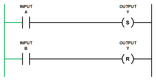
Ladder Logic Latch with SET & RESET Symbols
Let’s start with the Set (Latch) and Reset (Unlatch) logic. Remember Allen Bradley PLC’s use Latch and Unlatch symbols.
The rungs below show the basic code.
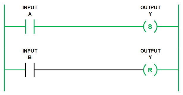
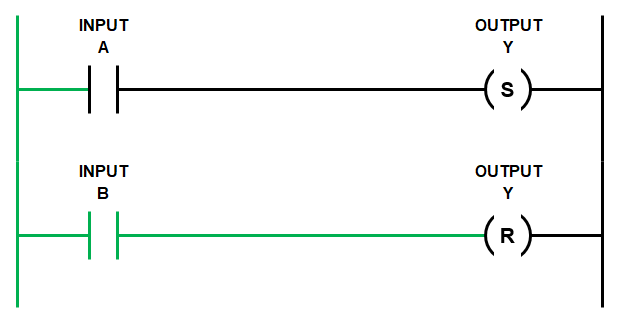
When both Input A and Input B are FALSE then the state of Output Y does not change. If Output Y is FALSE then it stays FALSE….
Ladder Logic Programming Examples – Ladder Latch
If Input A goes TRUE momentarily then the SET symbol changes the state of Output Y to TRUE.
Then, after subsequent scans, if Input A changes state to FALSE it does not affect the state of Output Y. In other words, Output Y is latched TRUE…
Ladder Logic Programming Examples – Ladder Latch (Set or Latch)
Only when Input B changes state to TRUE will the RESET symbol change the state of Output Y back to FALSE. In other words, Output Y is now unlatched….
Ladder Logic Programming Examples – Ladder Latch (Reset or Unlatch)
Remember the PLC scan runs from left to right and from top to bottom.
So if both Input A and Input B are TRUE at the same time, then in the ladder diagram above the first rung is evaluated and Output Y is set TRUE.
But, then the second rung is evaluated and Output Y is set FALSE.
Once the scan reaches the end of the entire program it will execute the state of Output Y as FALSE.
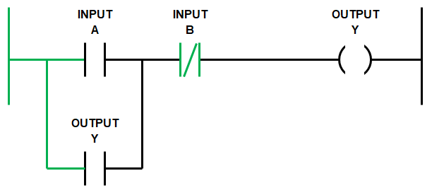
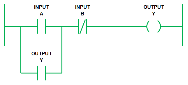
Ladder Logic Latch with Hold In Logic
Using hold in logic to achieve latching has a similar outcome to using Set (Latch) and Reset (Unlatch) symbols.
But with hold in logic both Input A and Input B are on the same rung as Output Y. Also, the way in which the latch is SET and RESET is done differently.
Notice that Input B is a normally closed (NC) contact symbol and Output Y is used twice and branched (or in parallel with Input A).
Ponder that thought for a second, let’s continue….
Ladder Logic Programming Examples – Ladder logic latch with hold in logic
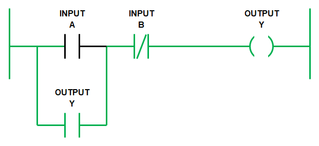
Remember the scan goes from left to right and top to bottom.
So the scan starts from the left hand side of the rung and moves right to Input A.
If Input A goes TRUE and Input B is FALSE then Output Y goes TRUE….
The scan continues on with the rest of the program and it cycles back to the rung.
Previously Output Y had changed state to TRUE, so now Output Y that is in a branch across Output A, also goes TRUE and there is no other change….
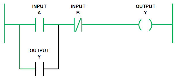
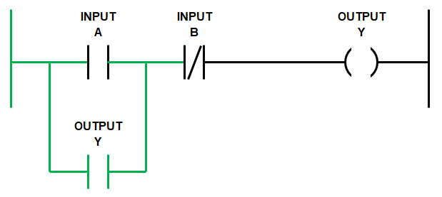
When the scan cycles back again from the top, if Input A goes FALSE, with Input B still FALSE, then Output Y stays TRUE.
This is because Output Y is held in by itself using the branch across Input A.
Notice that the logic flows from the left hand side rail through the Output Y branch and then through Input B to Output Y at the right hand side rail. Pretty cool…..
Ladder Logic Programming Examples – Ladder hold in logic (Latched)
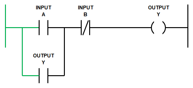
Once we have triggered the hold in logic using Input A, Output Y will remain latched even if Input A goes FALSE.
Output Y will remain latched TRUE until Input B goes TRUE. Because Input B is a normally closed (NC) contact symbol, when it goes TRUE, the logic flow is blocked and Output Y goes FALSE. Thus releasing the latch.
Remember the NC contact symbol works like a NOT statement, it’s reverse logic….
So, when the scan cycles back again from the top then Output Y, branched across Input A, also goes FALSE….
Ladder Logic Programming Examples – Ladder hold in logic (Unlatched)
Once Input B returns to the FALSE state we are back at the start, ready to initiate the latch again.
We can write out the logic expression above as…
IF (INPUT A OR OUTPUT Y) AND NOT (INPUT B) THEN OUTPUT Y.
Hold in logic is great to use because it simplifies your code. It enables us to place all the conditions that initiate and release latch in the same rung. This makes it easier to read and troubleshoot.
PLC Motor Control
Ladder logic for motor control can be accomplished using hold in logic. Remember it’s ok to also call it latching logic.
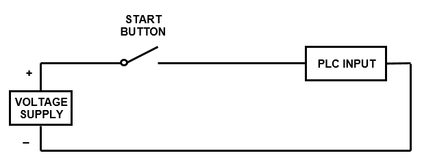
When we wire up the inputs to the PLC the start push button input is wired normally open (NO). So when the start button is pushed the PLC input changes state from FALSE to TRUE…
PLC Wiring Basics – Start button
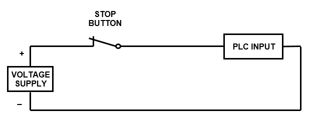
But the stop push button and thermal overload are always wired normally closed (NC). So when the stop button is pushed it changes from CLOSED to OPEN. In turn the PLC input changes state from TRUE to FALSE….
PLC Wiring Basics – Stop Button
In fact the rule of thumb is that any device that is required to stop the motor should be wired normally closed (NC), to make it “fail safe”.
The most common failures are wire break, device failure or PLC input failure.
Wiring the stop push button normally closed (NC) is done because when a failure occurs in the PLC input circuit it will, more often than not, lead to an open circuit which changes the state of the PLC input from TRUE to FALSE.
However, if we wire the stop PLC inputs as normally open (NO) and a failure occurs then the state of the PLC input does not change. It stays FALSE, even if the stop button is pressed, because there is an open circuit in the connection to the PLC input.
So if there is no change in state, we cannot tell the motor to stop in our ladder logic program. This is really bad!!!
So for any PLC input that is intended to stop the motor we need to..…
WIRE THE MOTOR STOP SIGNALS NORMALLY CLOSED AND USE A NORMALLY OPEN SYMBOLS IN THE PLC.
Now that we’ve grasped the concept of the fail safe stop input let’s move on to the motor control ladder logic programming example.
Motor Control Ladder Diagram
First up let’s list the required inputs and outputs for our motor control ladder diagram.
PLC manufacturers use different memory address allocation so the input output allocations used here are arbitrary address.
Below is the list of required inputs …..
Next let’s list the required outputs…..
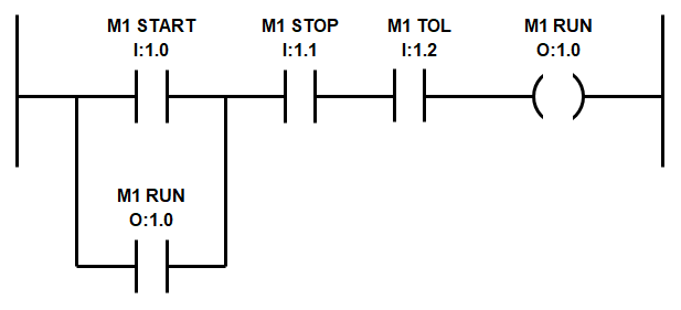
The ladder logic programming example uses the M1 START push button input to activate the M1 RUN output.
The M1 RUN output is used a second time to latch the M1 RUN output.
Both M1 STOP and M1 TOL are wired normally closed (NC) to the PLC inputs and thus need to be configured as normally open (NO) symbols in the logic.
So when either stop is activated the logic flow is broken and the latch is reset….
Ladder Logic Programming Examples – Motor Control Ladder Diagram
Remember, we must wire M1 Stop and M1 TOL using normally closed (NC) contacts to the PLC inputs to make it “fail safe” and for this motor control ladder diagram to work.
If you don’t know what the heck I’m talking about you’ve probably skipped straight to the motor control ladder diagram. Please….Go back and read the section above to get full bottle on latching logic…..It’s important!
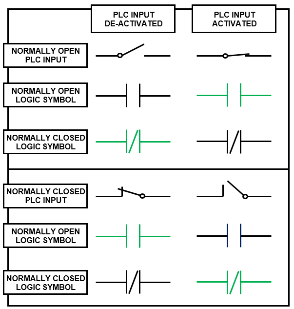
PLC Wiring Basics
If you are still a little confused about the different PLC wiring and ladder diagram symbol combinations and their different logic states then….DON’T PANIC!
To help out we’ve developed a nifty table which displays the different combinations of PLC digital input wiring and ladder logic symbols that can be used.
Further more, it outlines the logic state each of the ladder logic symbols depending on whether the PLC input is activated or de-activated. When the symbol is BLACK it’s state is FALSE and when the symbol is GREEN it’s state is TRUE.
PLC Wiring Basics and Ladder Logic Symbols
In the next section we’ll build on our newly discovered knowledge by exploring different PLC timer instructions, their PLC symbols, timing diagrams and operational description from various manufactures and brands.